

A Technical Site Survey Report is a field-verified baseline for rollout work; its value is in what it records, how it is evidenced, and how it gates planning and commissioning.
Executive Summary
- In telecom rollout, TSSR most commonly means Technical Site Survey Report: a site-visit record produced before installation so design, procurement, and installation can proceed without repeat visits or avoidable rework.
- There is no universal TSSR template; the practical rule is simple: anything that will be installed, modified, or relied on must be surveyed and documented to the level the downstream teams need.
- A useful TSSR is not just text fields: the control mechanism is that each recorded value is backed by photos (panoramas, antenna views, bracket/tilt evidence) so reviewing teams can verify the survey remotely.
- A real operator workbook typically separates existing versus planned/post-swap configurations using the same field set; errors then propagate directly into planning assumptions and installation scope.
- The civil scope is not a side-note: where the TSSR drives an itemised material take-off, a survey error becomes a procurement error before anyone reaches site.
- On an existing site, the chain is TSSR → planning → installation → commissioning (using the SCF) → drive/walk test → optimisation → acceptance/handover; the TSSR does not “become” the SCF.
- The highest-cost failures occur when as-surveyed and as-built diverge: wrong materials, invalid tower/power calculations, RF performance mismatch, rework, and delayed acceptance—then the next project inherits the wrong baseline.
What a TSSR is (and the two things it is not)
In telecom rollout work, TSSR most commonly stands for Technical Site Survey Report. It is prepared after a physical site visit and before installation starts, and its purpose is straightforward: capture the facts the project will rely on so that design, procurement, and installation can proceed without repeat site visits caused by missing or ambiguous information.
The acronym is overloaded in ways that can derail search results and internal conversations. TSSR is also used for Australia’s Telecommunications Sector Security Reforms (a cybersecurity regulation, unrelated to site survey work). And SCF in other telecom contexts can mean a Service Control Function in Intelligent Networks/CAMEL (unrelated to radio site commissioning). In this article, SCF means Site Configuration File, used to commission the site.
The practical framing is: a TSSR is not a generic “site survey” narrative. It is an engineering input document with downstream consumers, approvals, and consequences when it is wrong.
No universal template: the rule that decides what goes in
There is no universal TSSR template. Each operator, vendor, and rollout contractor tends to evolve their own workbook, field set, and sign-off pattern, and the content changes with the project scope (swap versus expansion, rooftop versus tower, MW backhaul versus fibre, power-system changes versus “like-for-like” additions).
The governing rule that makes the document predictable is: whatever is going to be installed, modified, or relied on at the site must be surveyed and documented in the TSSR. If a future decision depends on it, it must be measurable, recorded, and evidencable.
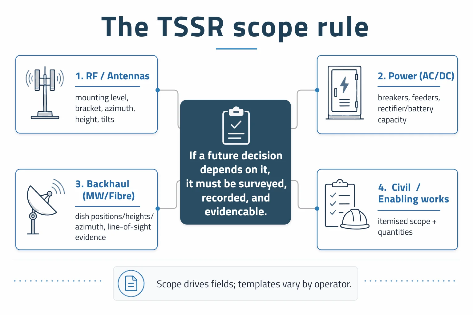
- If new antennas are being added, the TSSR needs mounting level availability, bracket details, and tilt evidence—not just “space available”.
- If rectifiers/batteries are being uprated, the TSSR needs breaker capacity, feeder details, and DC plant constraints—not just “power OK”.
- If equipment inside the shelter or equipment room is being added or removed, the TSSR needs the existing rack and cabinet inventory, what is going out, and the space, power and cabling that removal frees up—not just a note that the room was visited.
- Cooling and alarms are not conditional: every survey needs the air-conditioning units and their condition, and the full alarm set the site reports with its wiring back to the monitoring point. In a swap every alarm has to be re-mapped to the new equipment, so this is never someone else’s scope.
- If MW links are in scope, the TSSR needs dish positions, heights, azimuths, and line-of-sight evidence—not just “MW present”.
- If civil works are triggered, the TSSR needs an itemised scope and quantities—not a paragraph description.
What a TSSR records, section by section
A TSSR is usually organised into section families rather than one linear narrative. The exact field names vary by operator, but the same engineering needs recur.
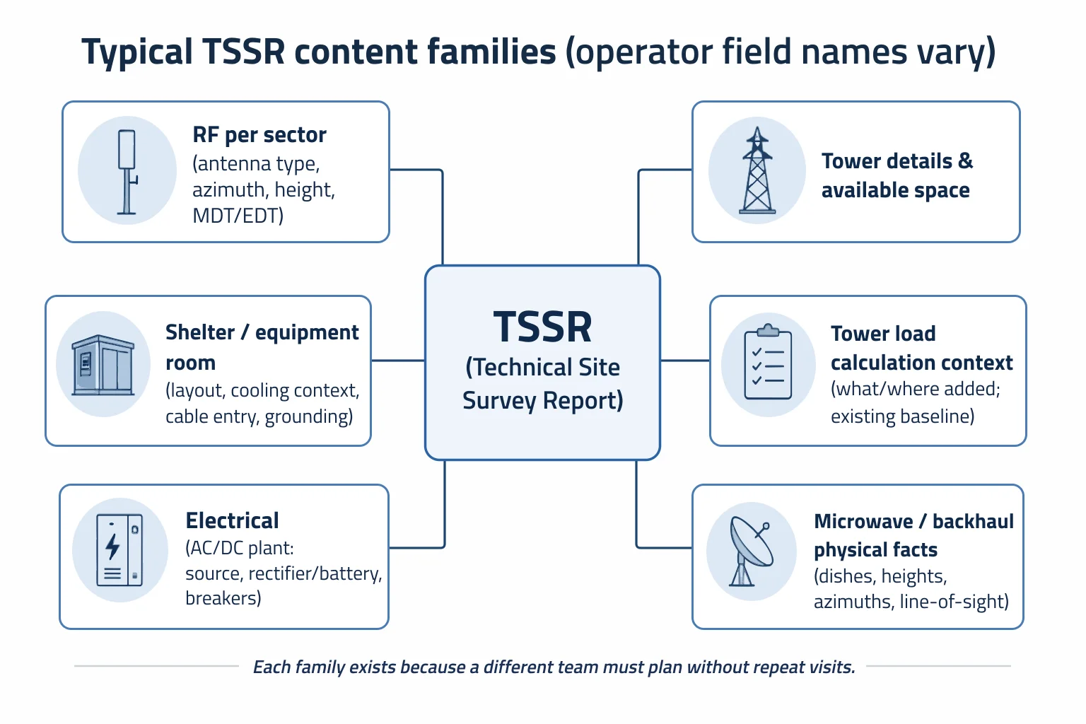
RF part (per sector)
The RF part records, per sector, the antenna type, azimuth, height, mechanical downtilt and electrical downtilt. In practice, this is the minimum set needed for radio access network (RAN) planners and installers to agree what is physically present and what will change.
Tower details and available space
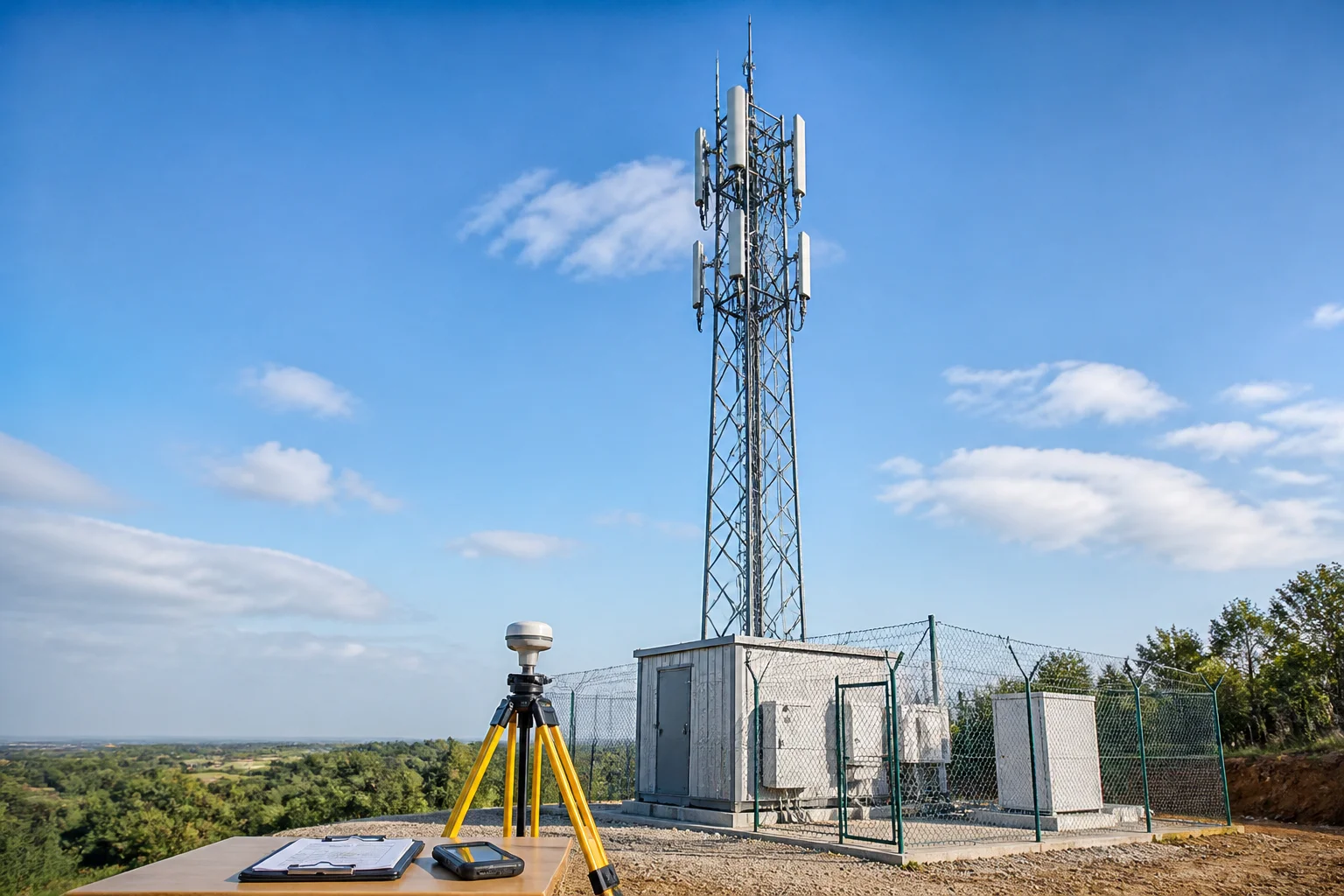
Tower details typically include tower type and height, existing equipment and mounting levels, and available space. The point is not documentation—it is to support safe mounting decisions and avoid discovering conflicts (or access constraints) during installation.
Shelter / equipment room details
For ground-based sites and indoor installations, the TSSR records layout, available space, cooling context, cable entry, and grounding, together with the equipment already installed in the room and any equipment the project will add or remove. These details drive rack placement, cable routing, and whether any enabling works are required before radio work can start. Removals matter as much as additions: decommissioned equipment releases floor space, breakers and cable routes that the new configuration may be counting on, and a removal that is planned but not recorded leaves the next project working from an inventory that no longer exists. The room’s cooling and alarm set belong in the same record: air-conditioning units with their rating and condition, and the full alarm set the site reports with its wiring back to the monitoring point. Neither carries radio traffic, which is why both are easy to omit, and both block acceptance when they are found missing or unwired at the end.
The alarms a TSSR should record in every case are door open or intrusion, smoke and fire, high temperature, water or flood, air-conditioning unit failure, mains failure, rectifier fault, battery alarms (low voltage and high battery temperature), and — where the site has one — generator alarms for fail and low fuel. Recorded only where they are installed: humidity, fire suppression system status, motion sensor or CCTV, and aviation obstruction light failure where it is wired to the shelter alarm panel.
Listing the alarms is not the same as surveying them, and this is where surveys usually fall short. For each one the TSSR should record:
- whether the sensor is present, missing or faulty;
- whether it actually works — ideally tested on site and confirmed in the OSS/NMS;
- which equipment and port it is wired to, and how it is named in the OSS/NMS;
- a photo of the sensor and of its wiring at the alarm port.
Swaps are where this matters most. When the old equipment comes out, every external alarm has to be rewired and re-mapped to the new equipment. If the TSSR does not record which sensor goes to which port, alarms are quietly lost at the swap and nobody notices until a door opens or an air-conditioning unit fails and nothing is reported. Sensors found missing or faulty should be flagged in the TSSR so they enter the scope and the material take-off, rather than being discovered at acceptance.
Tower load calculation context
A tower load calculation section exists to confirm the structure can carry the new equipment. Depending on the operator’s process, the TSSR may include the inputs needed for the structural check (what is being added, where it will be mounted, and what is already present) and/or the structural team’s confirmation outcome.
Electrical details (AC and DC plant)
Electrical details commonly cover the power source, rectifier and battery capacity, and available breakers. This is where “power available” is turned into verifiable constraints: what is actually installed, what headroom exists, and what protection/feeder limits could block the change. Power-related alarms — mains failure, rectifier, battery and generator — are recorded with the site alarm set in the shelter section rather than duplicated here. The air-conditioning units do belong in this section for their power draw and breaker allocation, because they consume part of the headroom the change is relying on.
Microwave details (where MW is present or planned)
Microwave details typically record existing and planned dishes, their heights and azimuths, and line of sight — and, equally, the indoor half of the link: the MW equipment installed inside the shelter or equipment room, its configuration, the ports and capacity in use, and the space available for what the project will add. A link is not surveyed when only the dish has been photographed. The TSSR is not the transmission design, but it captures the physical facts the transmission team needs to decide whether any MW action is pending.
The evidence rule: every value backed by a picture
A practical rule used in many rollout environments is: every piece of data written in a TSSR should be backed up by a picture . That typically means panoramic site views, antenna views, and close-ups that evidence the electrical tilt, mechanical tilt, and bracket configuration.
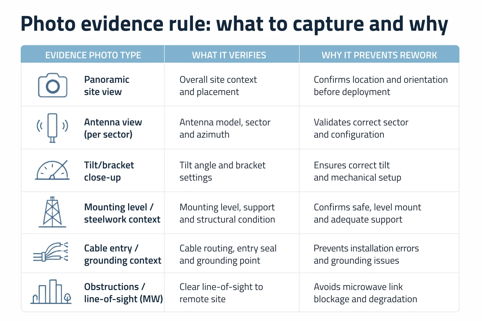
The reason the rule exists is often misunderstood. The photos are not there as documentation hygiene. They exist so that the reviewing teams can verify each recorded value after the survey is submitted, without needing to send another person to site simply to confirm whether the survey record is trustworthy.
- Where a value can be misread (tilt markings, mounting level, bracket type), a close-up is the evidence.
- Where context matters (compound layout, cable entry, obstructions), a panorama prevents false assumptions.
- Where safety and structural risk exist (tower loading, access constraints), photos reduce the chance of planning from an incorrect mental model.
Inside a real operator workbook (structure, not data)
In practice, TSSRs are often workbooks rather than single documents. A common pattern is a multi-sheet file where each sheet serves a specific downstream consumer and has its own sign-off expectations. The point here is the structure: no site identifiers, coordinates, vendor names, or real values are needed to understand why the workbook is organised this way.
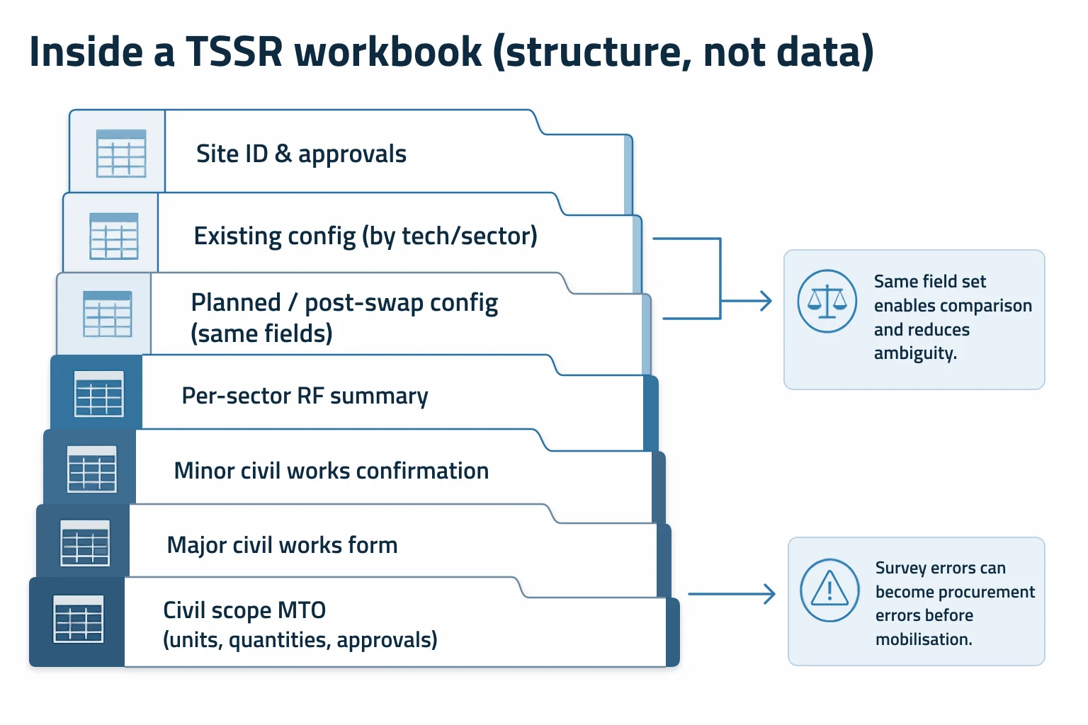
- A site identification sheet with an approval block (who surveyed, who reviewed, who approved, and when).
- Sheets that record the existing technologies/configuration per technology and per sector.
- A matching set of sheets that record the planned or post-swap configuration, using the same field set as the existing-state sheets.
- A per-sector RF summary sheet consolidating the sector-level physical configuration into a planner-readable view.
- Minor civil works confirmation that separates what design requires from what the field survey reports as feasible on site.
- A major civil works form for larger enabling works that require explicit scope and approvals.
- A civil scope sheet that carries an itemised material take-off with units and quantities and a multi-role approval block.
The operational consequence is that the survey can directly drive procurement. Where the workbook includes an itemised material take-off, a survey error becomes a procurement error before anyone reaches site: the wrong materials are ordered, mobilisation is planned around the wrong scope, and the first time the mistake is discovered is often during installation.
Where the TSSR sits: from survey to acceptance on an existing site
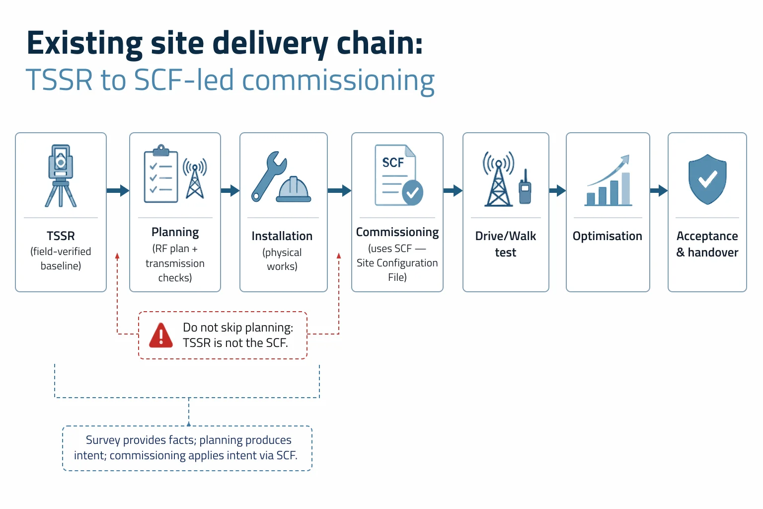
On an existing site (expansion or swap), the TSSR sits at the front of a defined chain. Net Technologies’ S‑ProM overview places site survey and acceptance ahead of site integration and commissioning in the lifecycle, which matches how most rollout organisations structure responsibilities.
- TSSR (field capture of the baseline and constraints).
- Planning (RF planning and any required coverage prediction; transmission/microwave checks whether any MW action is pending).
- Installation (physical works and equipment changes).
- Commissioning (performed using the SCF — Site Configuration File).
- Drive test, or walk test for indoor sites.
- Optimisation (drive/walk test reports reviewed alongside site performance and daily KPIs; parameter adjustments managed under the operator’s optimisation process).
- Tuning and troubleshooting (parameter and physical adjustments, with RF and technical-support involvement, until performance holds against the acceptance criteria).
- Acceptance and handover.
The key relationship is: the TSSR feeds planning, and planning produces the RF plan; the SCF is what commissioning is performed with. The survey does not “hand straight to the commissioning file”. The survey provides the verified physical facts; planning turns those facts into the configuration and parameter intent; commissioning applies that intent on the site, and tuning closes the gap between a site that is on air and a site that passes acceptance.
New sites follow a different sequence
New sites follow a different sequence from expansions and swaps. Treating them as the same process is a reliable way to mis-sequence responsibilities and approvals.
For a new site, the RF team carries out a study, proposes a location, and defines an acceptable search radius. The site acquisition team then checks whether a site can be acquired within that radius, and representatives from each relevant team typically visit to confirm there are no obstacles that would invalidate the candidate (access, physical constraints, obvious line-of-sight blockers, or other practical issues).
Only after those steps does the survey-to-acceptance chain described for existing sites apply. In other words: the survey-to-acceptance chain applies to existing sites, while new sites begin with RF study and site acquisition steps.
When as-surveyed and as-built disagree
The most expensive problems occur when the survey record and the built reality diverge. This can happen because the survey was wrong, because the installation deviated from the plan without being captured, or because the as-built update discipline failed.
- Wrong material orders (especially where the TSSR drives an itemised take-off).
- Rework and repeat site visits to correct mounting, cabling, or enabling works assumptions.
- RF performance that does not match the plan because the physical configuration is not what planning assumed.
- Invalid tower load or power calculations when the “what is installed” baseline is wrong.
- Delays in acceptance when verification fails or evidence is missing.
The compounding point is operationally simple: inaccurate as-built data becomes the starting point for the next project, so the error does not stop at the rollout wave that created it. It becomes embedded as “truth” until a later survey or failure forces a correction.
The control: verification and approval before anything proceeds
The approval gate is the part worth stating plainly: a TSSR is not advisory. The planning team and other specialist teams review the photo set and verify each detail after rollout subcontractors submit the survey.
These teams must approve the TSSR before any further action. For existing networks, the survey can also be compared against the existing database, which is a useful reference but cannot be fully relied on as ground truth.
Occasionally a detail cannot be confirmed from the pictures at all, and the rollout team is asked to verify the existing equipment during installation. This is not part of the normal process and should not be treated as one of the controls. Needing it means the survey was poor, and repeated resort to it means the subcontractor is not working to standard — the real remedy is to send the TSSR back, not to defer verification into the installation visit. Deferring it moves an unresolved question onto the critical path, where the cost of being wrong is a second mobilisation rather than a corrected form.
Who reads the report, and what each team takes from it
A TSSR exists because multiple teams need a shared, verifiable baseline. It is usually carried out by a rollout subcontractor and then consumed by planning, RF design, transmission, civil and structural engineering, the installation team, procurement, and the acceptance function.
- Planning / RF design: uses the sector-level physical facts (antenna type, azimuth, height, tilts) to produce the RF plan and resolve feasibility constraints early.
- Transmission / microwave: uses dish positions, heights, azimuths, and line-of-sight evidence to decide whether any MW action is pending.
- Civil works: uses minor/major civil forms and scope confirmations to sequence enabling works and approvals.
- Structural engineering: uses tower details and load-calculation context to confirm the structure can carry what is being added.
- Procurement: uses the itemised material take-off where present; this is why survey accuracy directly affects cost and schedule.
- Installation and commissioning: uses the verified baseline to execute physical work and then commission using the SCF.
RF propagation modelling and coverage prediction methods may be performed during planning as part of broader telecom network planning and design, but the method itself is a separate discipline; in this chain it matters mainly as a downstream consumer of the TSSR’s physical facts.
Need survey-to-commissioning clarity on a rollout?
Azura supports telecom engineering teams with survey definition, verification controls, and the handoff from TSSR into planning outputs and SCF-led commissioning — and the tuning and troubleshooting that carry a site from integration through to acceptance and handover.
Turning survey work into a dependable delivery baseline
Treating a TSSR as a dependable baseline is less about having “a form” and more about having a control: field capture that matches the scope, photo evidence that enables remote verification, and an approval gate that prevents downstream teams from planning off unverified values.
- Defining what the TSSR must capture for a given rollout scope (swap, expansion, new build) so that planning and installation are not forced into repeat visits.
- Reviewing or designing survey workbooks/templates so that existing versus planned states are separated cleanly and sign-offs are unambiguous.
- Setting verification and acceptance controls (what must be photo-evidenced; what can be cross-checked against the database; when a TSSR must be rejected and resubmitted).
- Supporting the handoff from TSSR into planning outputs, including the RF plan, and ensuring the SCF (Site Configuration File) used for commissioning is properly grounded in the verified baseline — then staying with the site through the RF and technical-support troubleshooting that commissioning alone does not resolve, until it is accepted and handed over. Commissioning with a correct SCF is a milestone, not the finish line.
Azura Consultancy provides engineering support across telecom planning and delivery contexts where survey quality, civil scope accuracy, and commissioning readiness determine whether the programme runs predictably or accumulates rework, supported by our technology strategy and implementation support capability.
Conclusion
A TSSR in telecom is best understood as a field-verified baseline document produced before installation so that planning, procurement, and delivery can proceed without avoidable surprises. There is no universal template; the deciding rule is whether the downstream teams will rely on a value—if they will, it must be surveyed, recorded, and evidencable.
The parts that most often justify the document are not the definition but the controls: photo evidence that enables verification, the approval gate that prevents work from proceeding on unverified data, and the discipline around as-built updates so the next project does not inherit a false baseline.
Reduce rework driven by bad baselines.
Where TSSR quality, civil take-offs, and as-built discipline are causing repeat visits or acceptance delays, Azura can help structure the controls and deliverables that prevent drift.