

A technical reference on designing chilled-water TES tank diffusers and using CFD to verify flow distribution, mixing risk, and thermocline stability before build or retrofit.
Executive Summary
- Diffuser design is a capacity and efficiency lever: poor distribution can destroy stratification and reduce usable TES volume without any change in tank size.
- The key design variable is momentum at the interface: discharge velocity, jet direction, and effective open area drive turbulence and entrainment across the thermocline.
- Short-circuiting (inlet-to-outlet path) is a common hidden failure mode; it can look acceptable on average temperatures while collapsing delivered ΔT at the plant.
- Pressure drop across the diffuser is not just a pump-energy issue; it changes flow split, can create asymmetry, and can push projects into unstable control regimes at part load.
- CFD verification should be structured around measurable acceptance criteria: velocity uniformity, turbulence intensity, thermocline thickness growth rate, and mixing/entrainment indicators during charge, discharge, and transient changeover.
- A credible CFD model needs boundary-condition discipline (flow, temperatures, turbulence model, buoyancy treatment) and a mesh strategy that resolves jets and the thermocline region; otherwise results become visually persuasive but decision-weak.
Why diffuser design is the make-or-break detail in chilled-water TES tanks
Thermal energy storage diffuser design has moved from a “detail design” topic to a programme risk item on many district cooling projects. Higher plant turndown, more frequent charge/discharge cycling, and retrofit upgrades mean tanks increasingly operate away from a single steady design point. In that regime, a diffuser that was ‘good enough’ at one flow can become the mechanism that collapses stratification at another.
This article is written for technical peers: district cooling designers, owners’ engineers, CFD analysts, and commissioning teams who need a decision-grade approach to TES tank diffuser design and verification. It covers diffuser function, geometry and placement choices, the failure modes that reduce effective tank capacity, and a practical CFD workflow to verify performance under charging, discharging, and partial-load operation.
For broader district cooling context (plant, network, and operating strategy), see Azura’s district cooling pillar at district cooling. For a general discussion of TES tanks and operational use cases (without going deep on diffuser methodology), the complementary article wise use of thermal energy storage tanks provides that wider framing.
What the diffuser is actually controlling: momentum, buoyancy, and entrainment
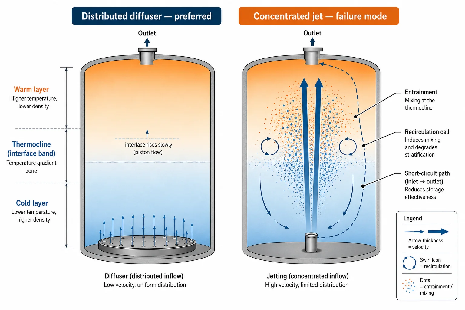
In a stratified chilled-water tank, the thermocline is the product: it is what turns geometric volume into usable storage. The diffuser’s job is to move water in and out while letting buoyancy do the separation work. When diffuser momentum dominates buoyancy locally, the tank behaves like a stirred vessel and the thermocline thickens.
Key physical levers the diffuser influences
- Local discharge velocity and jet structure (slot/orifice jets vs distributed seepage).
- Turbulence intensity and length scales near the inlet/outlet region (drives entrainment).
- Flow symmetry and azimuthal distribution (prevents preferential paths and dead zones).
- Recirculation cells near the floor/roof and around nozzles (creates mixing and short-circuit risk).
- Pressure drop across the diffuser (sets sensitivity to fouling, valve position, and flow maldistribution).
Why ‘average tank temperature’ is a misleading success metric
A diffuser can produce an acceptable average tank temperature while still failing operationally. Short-circuiting can deliver warmer return water to the plant during discharge, reducing delivered ΔT and increasing chiller lift. Conversely, mixing during charge can reduce the cold layer’s effective volume, forcing earlier mechanical cooling even though the tank still contains ‘cold’ energy in a mixed state.
Diffuser typologies and where each tends to fail
There is no single ‘best’ diffuser. The right choice depends on tank geometry, nozzle arrangement, operating flows, water quality, and how often the tank will cycle. The practical question is which design maintains acceptable distribution across the full operating envelope, including part-load and transients.
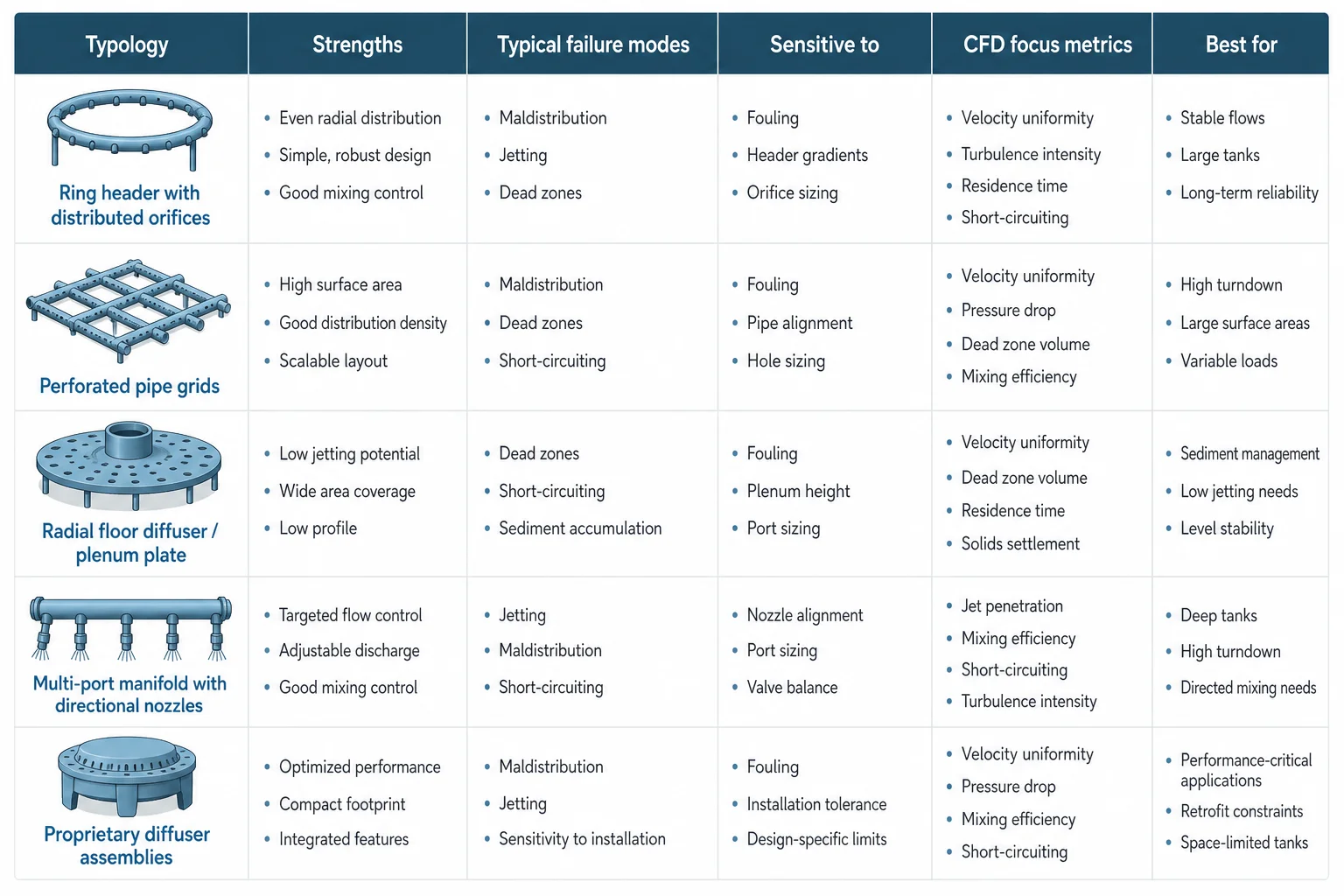
Typical diffuser families (chilled-water TES)
- Ring header with distributed orifices: simple, common; sensitive to orifice sizing, fouling, and header pressure gradient (maldistribution).
- Perforated pipe grids: can give good coverage; risk of preferential flow if the grid is not hydraulically balanced; installation tolerances matter.
- Radial floor diffuser / plenum plate: aims to reduce jetting by expanding area; can be robust, but can create recirculation if edges and gaps are not controlled.
- Multi-port manifold with directional nozzles: can manage momentum direction; higher risk of jet-driven mixing if ports are undersized or mis-aimed.
- Proprietary diffuser assemblies: often good distribution; diligence needed on pressure drop, fouling tolerance, and what ‘performance’ means in the vendor’s test conditions.
Selection cues that matter more than the brochure
- Turndown ratio: minimum stable flow without losing distribution uniformity.
- Reversibility: whether the same hardware supports both charge and discharge directions without creating a dominant jet path.
- Fouling and inspection: orifice blockage changes flow split first, then shows up as thermocline degradation later.
- Constructability: diffuser alignment, supports, and nozzle penetrations that are realistic to build and maintain.
Design risks to explicitly check (and how they show up in operation)
Across retrofit investigations, diffuser-related issues tend to be diagnosed late because the tank’s geometric volume is still present and instrumentation is often sparse. The operational symptom is usually plant-side: reduced ΔT, unexpected chiller run hours, or unstable supply temperature during transitions.
Failure modes worth treating as design checks
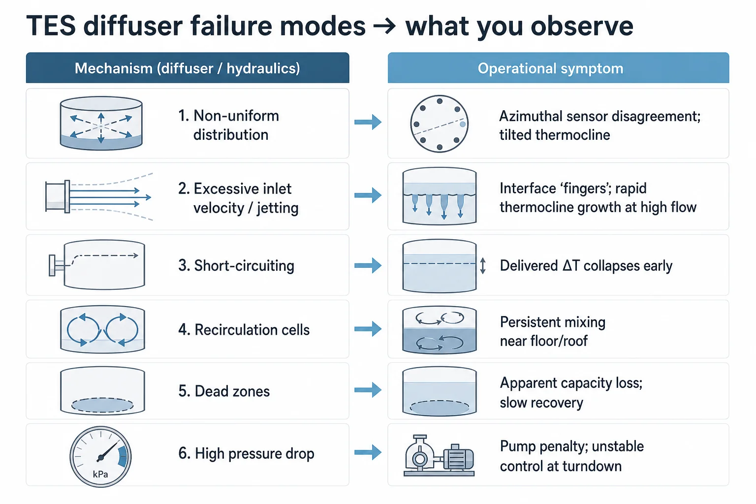
- Non-uniform distribution: one sector of the tank charges/discharges first; thermocline tilts and thickens; temperature sensors disagree azimuthally.
- Excessive inlet velocity / jetting: visible ‘fingers’ of cold or warm water penetrating the opposite layer; rapid thermocline growth with flow increases.
- Short-circuiting: inlet flow finds a preferential path to the outlet (often along walls or through a central core); delivered ΔT collapses before tank energy is exhausted.
- Recirculation cells: persistent vortices near the floor/roof or around penetrations that pull mixed water across the interface.
- Dead zones: stagnant regions that never fully charge/discharge; apparent capacity loss and slow recovery after cycling.
- High pressure drop: pump energy penalty plus sensitivity to valve position; can drive maldistribution if the header/branch network is not balanced.
These are diffuser and hydraulics issues first. Mechanical loads at tank nozzles and supports are a separate discipline — chilled water piping stress analysis — and should be handled as a parallel workstream rather than folded into the thermal verification model.
CFD verification workflow: what to model, what to measure, and what to accept
CFD analysis for thermal energy storage is often commissioned after a performance problem is suspected. It is more valuable when used earlier as a design gate: verify that the diffuser concept is physically capable of maintaining stratification across the full operating envelope before fabrication or retrofit.
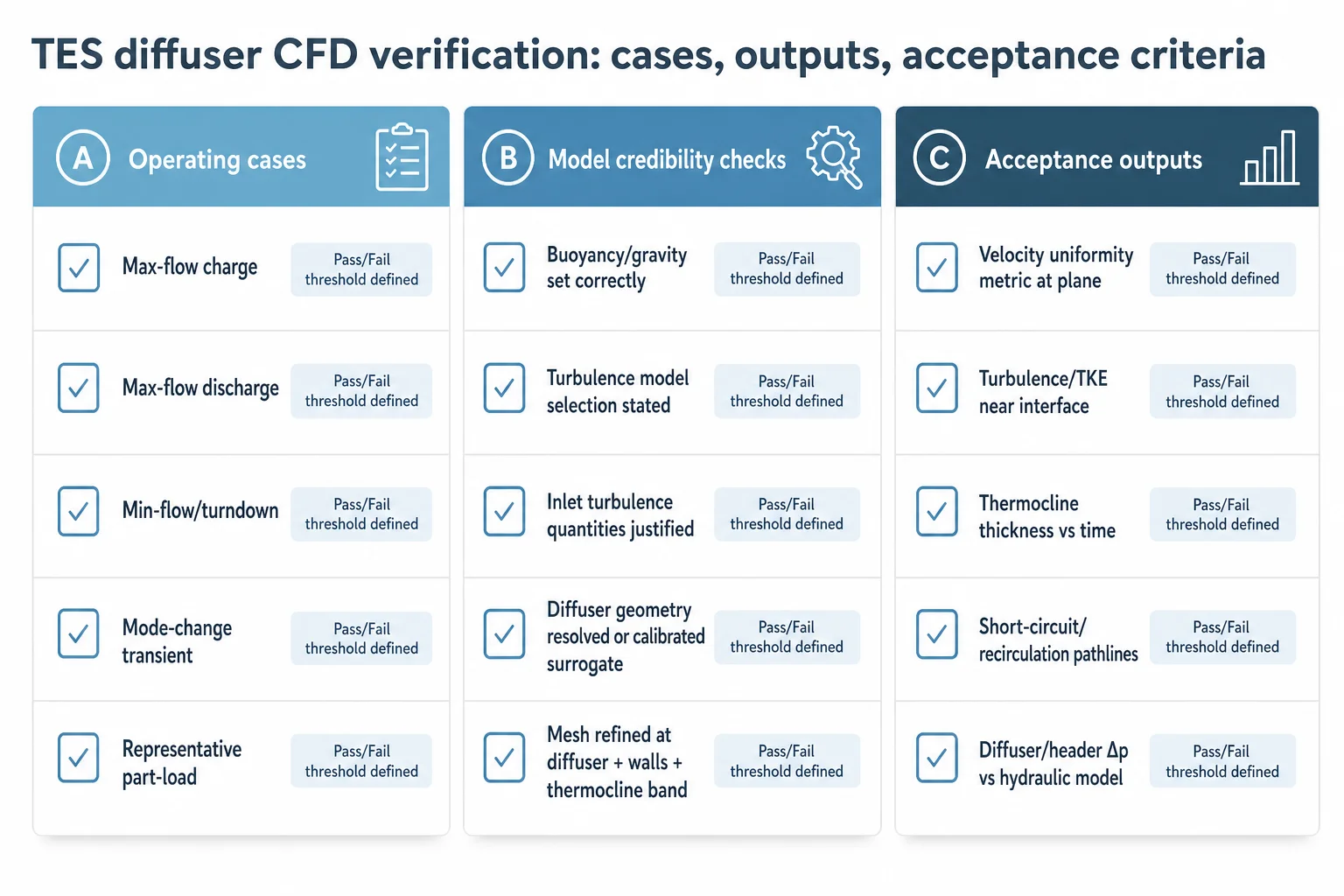
Step 1 — Define the verification cases (don’t model one ‘design point’)
- Charging at maximum flow (worst-case momentum input).
- Discharging at maximum flow (worst-case extraction pattern and outlet-induced recirculation).
- Minimum stable flow / turndown case (distribution uniformity often degrades here).
- Mode change transient (charge→discharge and discharge→charge), including valve sequencing assumptions.
- A representative partial-load case aligned to expected plant operation (e.g., night charge, day discharge).
Step 2 — Boundary conditions and physics settings that decide credibility
- Use buoyancy-enabled modelling (Boussinesq or full density variation as appropriate) with gravity correctly oriented; stratification is a buoyancy problem.
- Treat turbulence modelling as a choice with consequences: a steady RANS run may miss transient mixing; URANS/LES may be warranted for jet-driven designs depending on scale and budget.
- Set inlet turbulence quantities defensibly; ‘default’ values can over- or under-predict mixing.
- Model the diffuser geometry at the level that controls jets (ports, slots, perforations) or use a validated porous-jump/pressure-loss surrogate with documented calibration.
Step 3 — Mesh strategy: resolve what causes mixing
A mesh that is too coarse at the diffuser outlets will smear jets and underpredict entrainment; a mesh that is too coarse across the thermocline will artificially diffuse the interface. Practical meshing focuses refinement in three zones: (1) diffuser discharge region, (2) near-wall regions where short-circuiting can develop, and (3) the thermocline band where gradients are steep.
Step 4 — Outputs and acceptance criteria (make the CFD auditable)
- Velocity distribution at a defined plane above/below the diffuser: uniformity metrics (e.g., coefficient of variation) rather than ‘looks even’.
- Turbulence intensity / turbulent kinetic energy near the interface region during peak flow cases.
- Temperature field slices over time: thermocline thickness evolution and any interface ‘penetration’ features.
- Recirculation identification: streamline/pathline analysis showing any direct inlet-to-outlet paths.
- Pressure drop across diffuser and header: confirm it aligns with pump and control assumptions.
Using CFD results in design decisions: iterate geometry, not just report plots
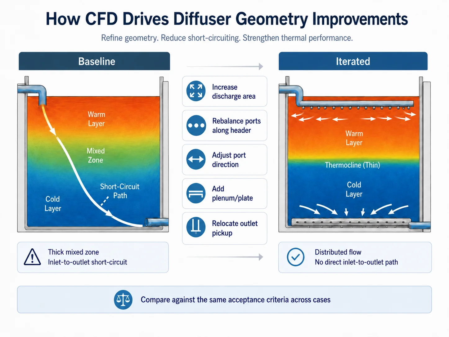
A common failure mode in CFD studies is producing high-quality images without changing the design. For diffuser work, the value is in iteration: use the model to test a small number of geometry changes that directly target the diagnosed mechanism (jetting, maldistribution, recirculation, short-circuiting).
Typical geometry changes that CFD can de-risk quickly
- Increase total discharge area to reduce velocity (while checking for new dead zones at low flow).
- Rebalance orifice/port sizing along headers to flatten flow distribution.
- Change port directionality to align with buoyancy (avoid upward jets during cold-water injection, avoid downward jets during warm-water injection).
- Introduce a plenum/plate to convert a jet into a low-momentum seepage field.
- Move outlet pickup away from the inlet influence zone to eliminate short-circuit paths.
Where projects already have tanks in operation, CFD can be paired with targeted site measurements (limited temperature rakes, differential pressure across diffuser, flow confirmation) to calibrate the model. That calibration step is often the difference between a ‘nice study’ and a retrofit design that works first time.
For adjacent system-level implications (how TES interacts with plant sequencing, heat pumps, and boundary definitions), the article Strategic Heat Pump Placement in Data Centres provides a useful lens on how thermal storage fits into broader operational strategies.
Design checklist: diffuser sizing and CFD acceptance criteria for chilled-water TES
A. Diffuser design checks (before CFD)
- Define operating envelope: max/min flow, expected cycling frequency, temperature programme, and mode-change sequencing assumptions.
- Set a momentum target: translate allowable mixing risk into a maximum local discharge velocity or jet momentum flux at the diffuser outlets (project-specific).
- Hydraulic balance: confirm header/branch losses do not create maldistribution at both max and min flow; check sensitivity to partial blockage/fouling.
- Pressure drop budget: confirm diffuser Δp is compatible with pump head and control valve authority without forcing unstable control at turndown.
- Geometry/placement: verify inlet/outlet locations and directions do not create an obvious short-circuit path along walls or a central core.
B. CFD verification acceptance outputs (per operating case)
- Velocity uniformity at a defined plane: report min/mean/max and a uniformity statistic; identify any jets exceeding the momentum target.
- Recirculation/short-circuit check: demonstrate no persistent inlet-to-outlet streamline path under steady and transient cases.
- Thermocline behaviour: report thermocline thickness over time and its growth rate during the first part of charge/discharge (where damage is often done).
- Mixing indicator: quantify entrainment across the interface (e.g., volume fraction of mixed-temperature band) rather than relying on colour plots.
- Δp confirmation: report diffuser and header pressure losses and compare to hydraulic model assumptions.
C. Commissioning and instrumentation implications
- Temperature measurement strategy: minimum sensor density to observe thermocline position and detect tilt; avoid single-point ‘top and bottom only’ instrumentation.
- Flow confirmation: measurement points to validate modelled flow splits (especially where multiple inlets/outlets exist).
- Operational constraints: define any flow ramp-rate limits or minimum-flow constraints needed to preserve stratification during transitions. These limits also reduce thermal-cycling demand at the tank nozzles and connected headers — see chilled water pipe flexibility analysis.
Need to verify a TES diffuser before build or retrofit?
Azura supports chilled-water TES tank diffuser design, hydraulic assessment, and CFD verification to reduce mixing risk and protect usable storage capacity.
What this means for district cooling project teams
On district cooling projects, TES tanks are often justified on peak-shaving, resilience, and tariff optimisation. Those benefits assume the tank behaves as stratified storage across the actual operating envelope. Diffuser underperformance is a common reason the realised benefit falls short: the tank volume exists, but the usable stratified volume does not.
In practice, diffuser design and CFD verification work best as a single integrated package: hydraulic sizing and pressure-drop discipline to ensure distribution, followed by CFD to verify mixing risk and short-circuiting across charge/discharge/turndown and transient cases. Azura’s capability in this area sits within Specialized Engineering Services, and connects naturally to district-scale delivery contexts covered on District Energy Tri-Generation.
- New-build TES: verify diffuser performance before fabrication; avoid late-stage ‘fixes’ that are expensive once internals are installed.
- Retrofit TES: use CFD to test modifications (additional ports, plenum plates, header changes) before shutdown windows.
- Operations support: translate CFD findings into ramp-rate limits, minimum-flow constraints, and instrumentation requirements that keep stratification stable in real control regimes.
Conclusion
Thermal energy storage diffuser design is not an accessory to a chilled-water TES tank; it is the mechanism that preserves stratification and therefore determines usable capacity and delivered ΔT. The recurring failure modes—jet-driven mixing, maldistribution, recirculation, and short-circuiting—are predictable and can be treated as explicit design checks rather than post-hoc troubleshooting.
CFD verification is most defensible when it is framed around acceptance criteria and multiple operating cases, not a single steady design point. When diffuser geometry, hydraulics, and CFD outputs are kept aligned, projects can commission TES tanks that behave as designed across charging, discharging, and part-load operation.
Make TES performance auditable, not assumed.
For district cooling programmes where storage performance is material, Azura can structure diffuser design and CFD verification around acceptance criteria and commissioning-ready outputs.
References
- District Cooling Best Practice Guide — International District Energy Association (IDEA) (2020-01-01)
- ASHRAE Handbook — HVAC Systems and Equipment (Thermal Storage chapter) — ASHRAE (2024-06-01)
- Thermal stratification in chilled — water storage tanks: influence of inlet momentum and diffuser configuration (review literature) — International Journal of Heat and Mass Transfer (various authors) (2020-01-01)
- ANSI/ASHRAE Standard 150 — Method of Testing the Performance of Cool Storage Systems — ASHRAE (2019-01-01)