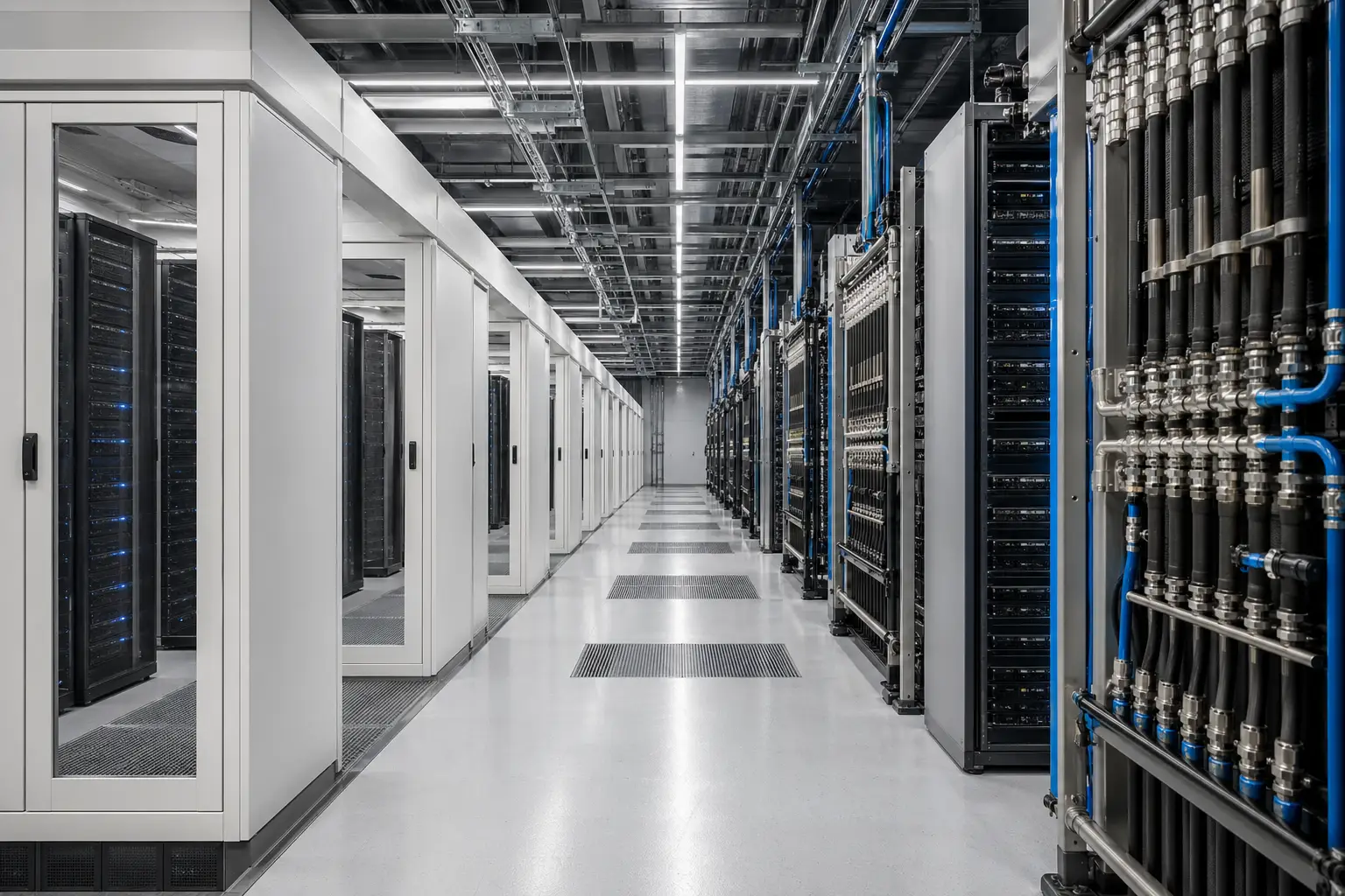


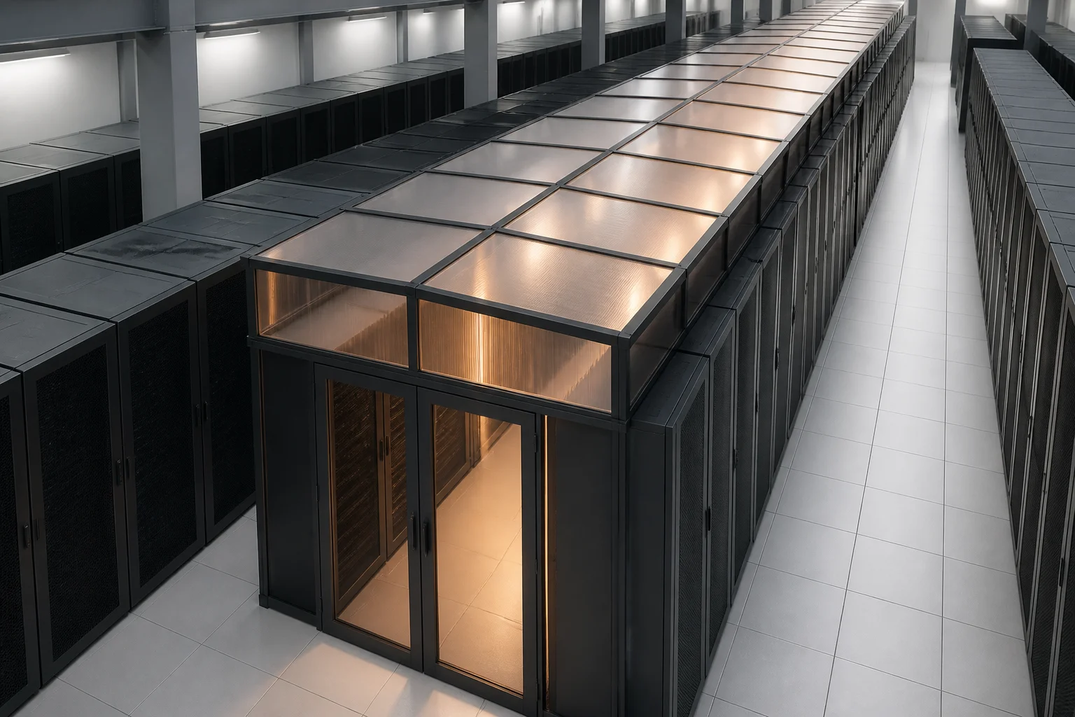
A step-by-step engineering workflow to prove a containment change will work in a live, air-cooled hall before racks are moved.
Executive Summary
- There is no published ASHRAE-defined rack-kW “air cooling ceiling”; widely quoted 30–40 kW/rack limits are not traceable to a primary standard, and operator views on when liquid becomes necessary are widely split.
- The retrofit risk is rarely “containment hardware” in isolation; it is bypass air and recirculation created by leakage, return-path short-circuiting, and mismatched IT-versus-CRAH airflow that containment can amplify.
- A credible retrofit case starts with measurement, then a model calibrated to those measurements; solver convergence is not proof the model represents the real hall.
- Field evidence exists that bundled airflow-management retrofits can release stranded capacity in legacy halls (e.g., LBNL/DOE reporting ~21% more usable cooling capacity and ~8% lower fan energy), but published evidence isolating hot-aisle containment’s incremental effect is scarce—so verification must close the loop.
- Scenario comparison should treat rack positions as an input variable, not a fixed background condition; the “best” containment layout can change if high-flow racks move or if CRAH states differ in maintenance modes.
- The decision outputs are (1) an approved change set (physical works + controls changes + operational constraints) and (2) a rack-move sequence; they are related but not the same deliverable.
- Hybrid-with-containment remains a live pattern; rear-door heat exchangers and in-rack liquid-to-air are product-dependent, and CDU wet weight can be a practical access and floor-loading constraint that must be checked early.
Why verification matters, and the entry condition for a retrofit
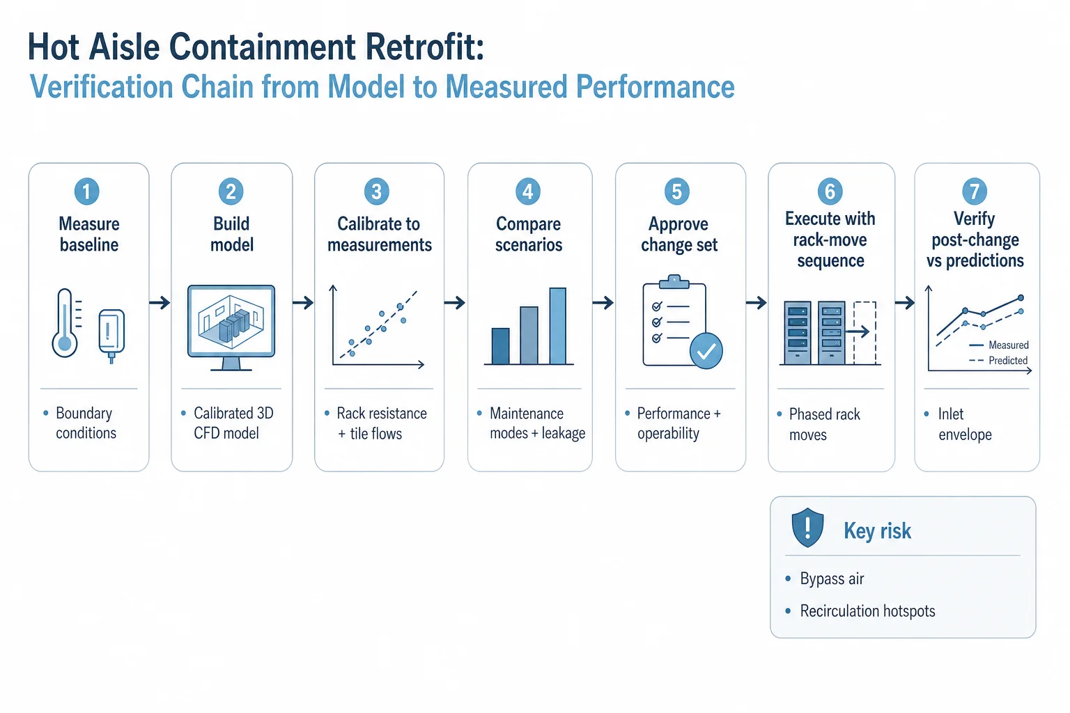
A hot aisle containment (HAC) retrofit is often treated as a procurement exercise: panels, doors, roof, fire interfaces, and an install plan. In a live data hall, the engineering reality is different. Containment changes the pressure field and the return-air path. If the hall already has leakage, return short-circuiting, or airflow imbalance, containment can turn an efficiency issue into a hotspot issue. That is why the retrofit needs an evidence chain: measure → model → calibrate → compare scenarios → approve a change set → execute with a rack-move sequence → verify against predictions.
A common failure in retrofit conversations is the idea that air cooling has a universal ceiling at “30–40 kW per rack”. That figure is widely quoted, but it is not traceable to an ASHRAE standard or a peer-reviewed universal limit. ASHRAE’s current framing is functional—liquid/Technology Cooling Systems become relevant where traditional air-based cooling becomes insufficient—rather than a single rack-kW threshold.
Operator responses reinforce why a single threshold is not defensible. In Uptime Institute’s 2025 Cooling Systems Survey (786 respondents), the reported point where air becomes too costly or inefficient and direct liquid cooling is considered necessary spans the full range: ~7% chose 1–9 kW, 12% chose 10–19, 14% chose 20–29, 11% chose 30–39, 13% chose 40–49, 18% chose 50–59, and 25% chose 60 kW or above. This is industry opinion, not an experimental thermal limit—but it directly refutes the idea that the sector operates with a settled 30–40 kW boundary. AFCOM’s 2026 respondents are similarly split, with 20% placing the threshold at 21–40 kW, 20% at 41–60 kW, and 20% at 61–80 kW, with the remainder above or below.
The physical reason there is no simple rack-kW ceiling is airflow mechanics. DOE airflow-management guidance treats cooling performance as a balance between IT airflow demand and air-handler airflow delivery, and distinguishes bypass air (air that does not cool IT and depresses return temperature) from recirculation (hot exhaust returning to equipment intakes and creating hotspots). Plenum resistance, perforated-tile characteristics, leakage paths, rack airflow demand, and the return path determine how much of nominal cooling capacity actually reaches server intakes. Under carefully managed airflow conditions, Intel/T-Systems demonstrated conventional CRAH-based air cooling at more than 20 kW per rack; that single point shows why a low universal threshold cannot be inferred from rack power alone.
The retrofit remains a live question because the installed base is still largely air-cooled and legacy-heavy (Uptime Institute is a common reference point on this), so many operators are improving airflow management rather than converting entire halls to liquid. Cooling-adoption data supports that: Uptime’s 2025 owner/operator survey reported 75% using perimeter air cooling and 22% reporting direct liquid cooling (multiple selections allowed; close-coupled air 32%, fresh-air 29%, indirect 26%). In the same survey, 46% named ease of retrofit into existing infrastructure as one of the two most important factors for direct liquid cooling viability. AFCOM’s 2026 survey reports 36% already have “liquid cooling” deployed and 28% plan adoption within 12–24 months—but the survey populations and categories differ, so the 22% and 36% figures should not be treated as a growth rate.
Baseline measurement and calibration: what to measure before any containment work
The baseline step is not “collect some temperatures”. It is to establish boundary conditions that a model can be held to: what heat is being generated, where it enters the air, how air is delivered, and how it returns. Without that, a CFD run is a picture, not evidence.
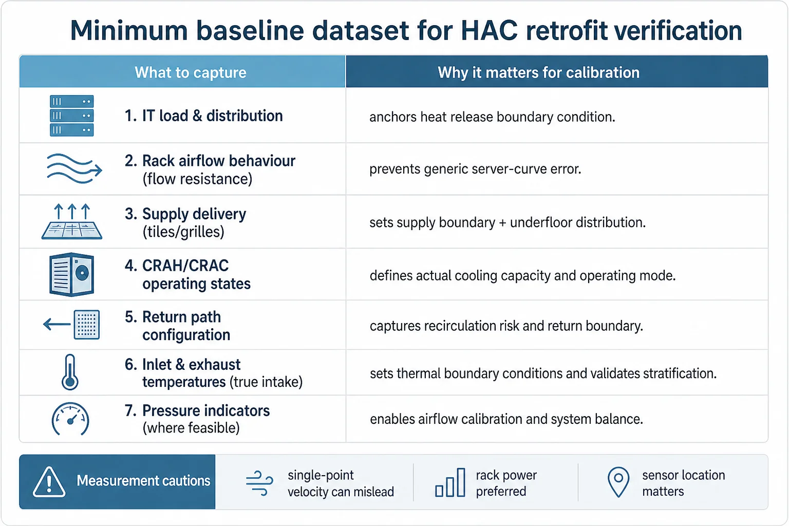
Minimum baseline dataset (practical, live-hall oriented)
- IT load and distribution: rack-level power where practical; if only PDU/row data exists, document aggregation assumptions and uncertainty.
- Rack airflow behaviour: where possible, characterise rack/system flow resistance from measured data rather than assuming a generic server curve; this becomes load-bearing in calibration.
- Supply delivery: tile or grille locations and types; measured flow characteristics for representative tiles/grilles (recognising uncertainty), and any dampers/blanking panels in the raised floor.
- CRAH/CRAC operating states: supply temperature, fan speeds/airflow settings, coil conditions, and which units are actually in service (including any “unrecorded” local overrides).
- Return path: ceiling plenum configuration, return grilles/ducts, obstructions, and any return-air short-circuit paths (e.g., open ceiling voids, cable trays creating unintended pathways).
- Inlet and exhaust temperatures: measured as close to the true IT intake as practical; document sensor placement and any offsets from the intake plane.
- Pressure indicators (where feasible): differential pressure across containment boundaries or representative points to detect leakage-driven bypass and unintended flow paths.
Measurement cautions that materially affect credibility
DOE data-collection guidance flags three recurring pitfalls. First, a single-point air-velocity measurement can be misleading in turbulent, non-uniform flows—especially near tiles, underfloor obstructions, or within mixing zones. Second, rack power measurements are preferable where practical because they anchor heat release more directly than inferred averages. Third, temperature sensors placed even a modest distance from the true IT intake can produce erroneous “inlet temperature” readings; for verification, the measurement location matters as much as the number of points.
A useful precedent for the overall pattern is a DOE/Lawrence Berkeley National Laboratory retrofit in an approximately 40-year-old facility. The work included return-air/plenum changes, CRAH ducting, hot-aisle strip curtains, and other airflow corrections. Reported results included about a 21% increase in usable cooling capacity, roughly 8% lower fan energy, elimination of most hotspots, a roughly 3°F increase in cooling setpoint, and the ability to shut down one 15-ton cooling unit to standby. The key caveat is that this is a bundled retrofit: the results are not attributable to containment alone. The value here is the workflow precedent—measure, change, measure—and the demonstration that airflow corrections can release stranded capacity in an operating legacy hall.
CFD calibration and what it can—and cannot—claim for a retrofit decision
CFD is the right tool for comparing retrofit scenarios because it can expose recirculation patterns, bypass pathways, and tile-flow imbalance before physical work is done. The risk is overclaiming what the model proves. ASHRAE research project RP-1675 (“Guidance for Data Center CFD”) was established specifically to benchmark CFD models against experimental measurements and develop modelling guidance across CRAH representation, perforated tiles, raised-floor structures, non-uniform rack power, and over- and under-supplied airflow conditions. A peer-reviewed 2024 paper summarises that ASHRAE-funded work.
Why no single “CFD accuracy” figure is defensible
Published validation results show wide variability. RP-1675’s literature review reports examples ranging from ~4% average / ~7% maximum error in perforated-tile flow in one validated model to roughly ~8% RMSE / ~20% maximum error in another. For room temperature predictions, one study overpredicted by ~3°C on average with a ~7°C maximum. A 135-rack validation found ~83% of racks within ±7°C, but with a local maximum error as large as 19°C. These figures are attributable to the studies reviewed; the point is that they demonstrate variability rather than a normal specification.
Some controlled configurations show tighter agreement. Athavale et al. reported average discrepancy below ~4% for total tile airflow and about ~1.7°C for rack-inlet temperature, with uniform rack loads around 10 kW. This is attributable to that test configuration; it is not a generic guarantee that an operational hall model will achieve the same.
A 2026 operational-data-centre study combined measurements using adjustable server simulators with a calibrated CFD representation of racks and airflow, reporting strong agreement in rack inlet/outlet temperature behaviour across several server-layout cases. A key methodological point is that server flow resistance was calibrated from measured data rather than treated as an assumed, unverified digital replica.
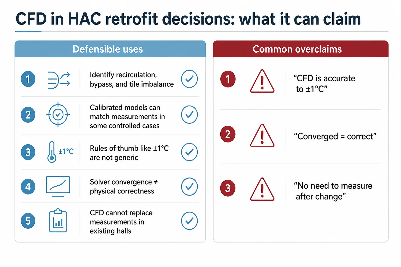
Five claims to keep honest in retrofit decision-making
- CFD can identify likely recirculation, bypass, tile-flow imbalance, and rack-inlet temperature patterns before a physical change is made. This is supported by ASHRAE/DOE guidance and validation studies.
- A calibrated model can reproduce measurements closely in some controlled configurations. Examples exist (e.g., ~1.7°C rack-inlet discrepancy and <~4% aggregate flow error) but they are configuration-specific.
- Rules of thumb like “data-centre CFD is normally accurate to ±1°C” or “±5%” are widely repeated but not defensible as general claims; published validation ranges vary markedly.
- Numerical solver convergence is not sufficient to prove physical correctness; ASHRAE guidance is explicit that a converged solution can still be wrong due to boundary-condition or modelling errors.
- CFD cannot replace measurements in an existing hall as a general proposition; measurements establish credible boundary conditions and provide the check that the model represents the real system.
Retrofit complications that dominate error—even when the CFD solver converges
The practical limit of CFD in a retrofit is epistemic: the model predicts the physics represented by its geometry, boundary conditions, and component models. In a live hall, the biggest deltas are often not in the turbulence model —they are in what was not known or not captured.
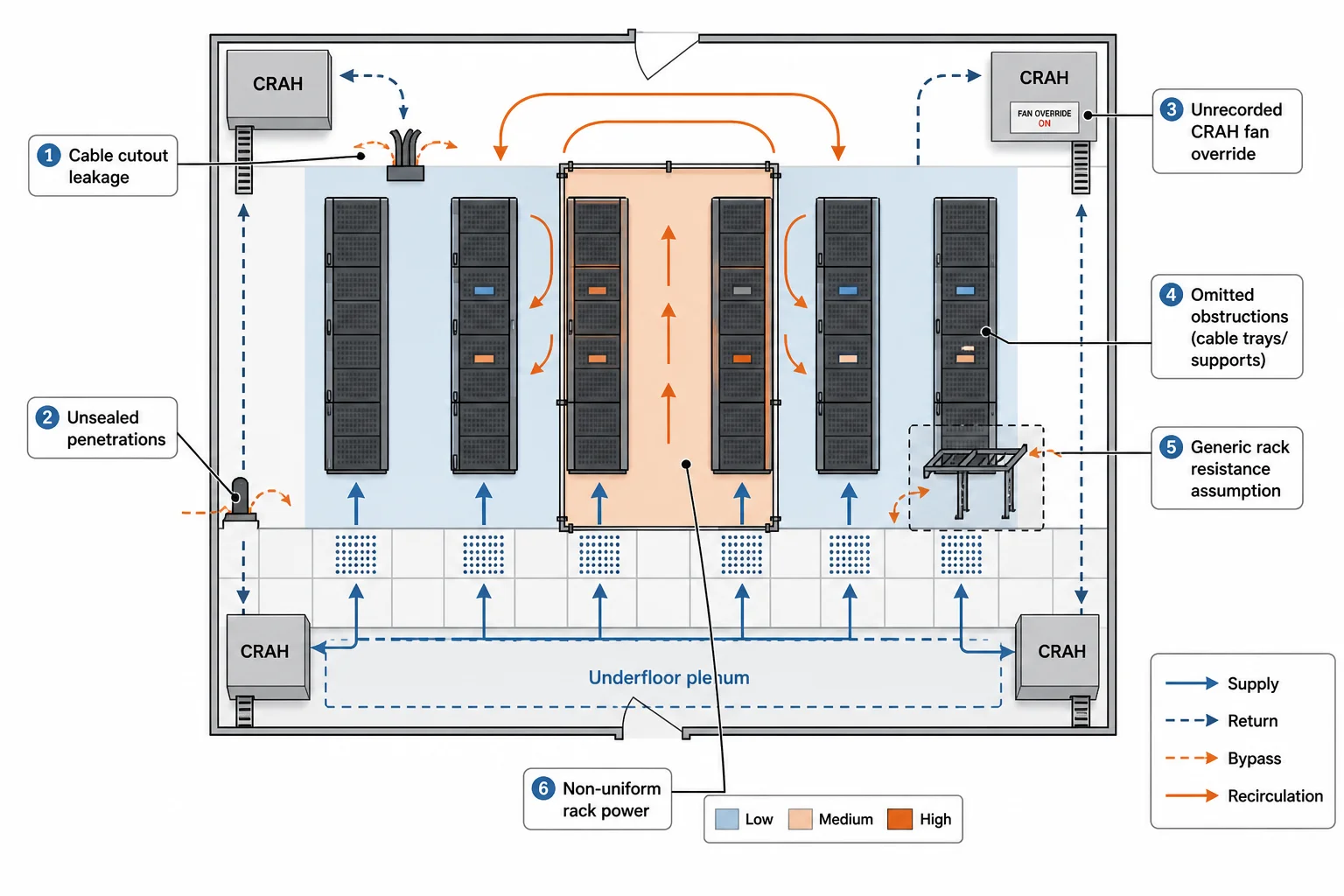
Common live-hall complications to surface explicitly
- Cable cutout leakage and unsealed penetrations: small areas can become dominant bypass paths once containment changes pressure differentials.
- Unrecorded CRAH/CRAC states: local fan overrides, failed actuators, or maintenance-mode configurations that are not reflected in BMS trend data.
- Oversimplified server/rack resistance curves: assuming a generic airflow curve can misstate rack demand; calibrating flow resistance from measurement is often the difference between a credible model and a misleading one.
- Obstructions and ‘minor’ geometry: cable trays, underfloor supports, poorly documented baffles, and temporary storage can materially alter underfloor distribution and return mixing.
- Non-uniform rack power and temporal variability: peak-versus-average loads, workload-driven changes, and partial population of cabinets can change local conditions enough to invalidate a single steady-state assumption.
These issues also explain why retrofit verification is not a one-shot study. The workflow needs explicit uncertainty management: identify which unknowns can change the decision, then either measure them, bound them, or test them as sensitivity cases (the same evidence-and-risk discipline used in Azura’s technical due diligence services) so the approved change set is robust to operational variability.
Scenario comparison: treat rack positions as an input variable
Once a baseline is measured and the model is calibrated, the value comes from comparing scenarios that reflect how the hall will actually operate. A frequent mistake is to treat the IT layout as fixed and only vary the containment hardware. In a retrofit, rack positions are an input variable: the same containment design can behave differently if high-flow racks move, if a row becomes partially populated, or if an “average” row becomes the next high-density zone.
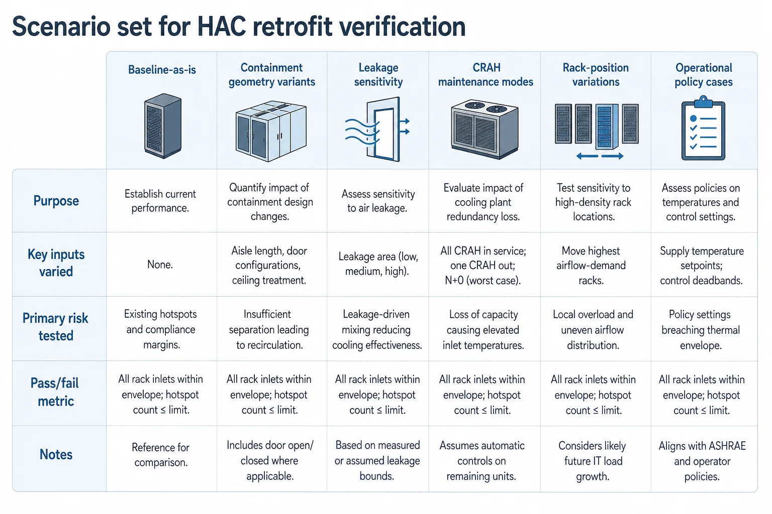
A practical scenario set for HAC retrofit verification
- Baseline-as-is: current layout and current CRAH states, used as the calibration anchor.
- Containment geometry variants: roof height/closure, door strategy, end-of-row sealing, and any planned return-path changes (e.g., ducted returns vs open plenum).
- Leakage sensitivity: explicit cases for known leakage paths (cable cutouts, tile gaps, top-of-rack openings) to test whether the design is fragile to imperfect sealing.
- CRAH state variations: credible maintenance modes (one unit out, reduced airflow, altered setpoint) to avoid approving a design that only works in the ‘all-units-healthy’ state — which is what concurrent maintainability requires of a Data Center Tier III facility.
- Rack-position variations: move the highest airflow-demand racks within the contained zone to test whether hotspot risk follows rack placement; this is often where a retrofit fails operationally.
- Operational policy cases: setpoint changes (within the intended operating envelope) and excursion policies, to ensure the retrofit does not rely on an unrealistic “perfect control” assumption.
The decision criterion should be expressed as a bounded claim: which racks are predicted to violate intake limits under which scenarios, and what design or operational changes remove that risk. This is also where the bypass-versus-recirculation distinction matters: a scenario that improves average return temperature can still be unacceptable if it increases recirculation hotspots at specific cabinets.
Approved change set and rack-move sequencing: two different deliverables
A containment retrofit that is technically sound can still fail operationally if the programme does not distinguish between what is being built and how the hall is transitioned. The verification chain should therefore output two distinct deliverables.
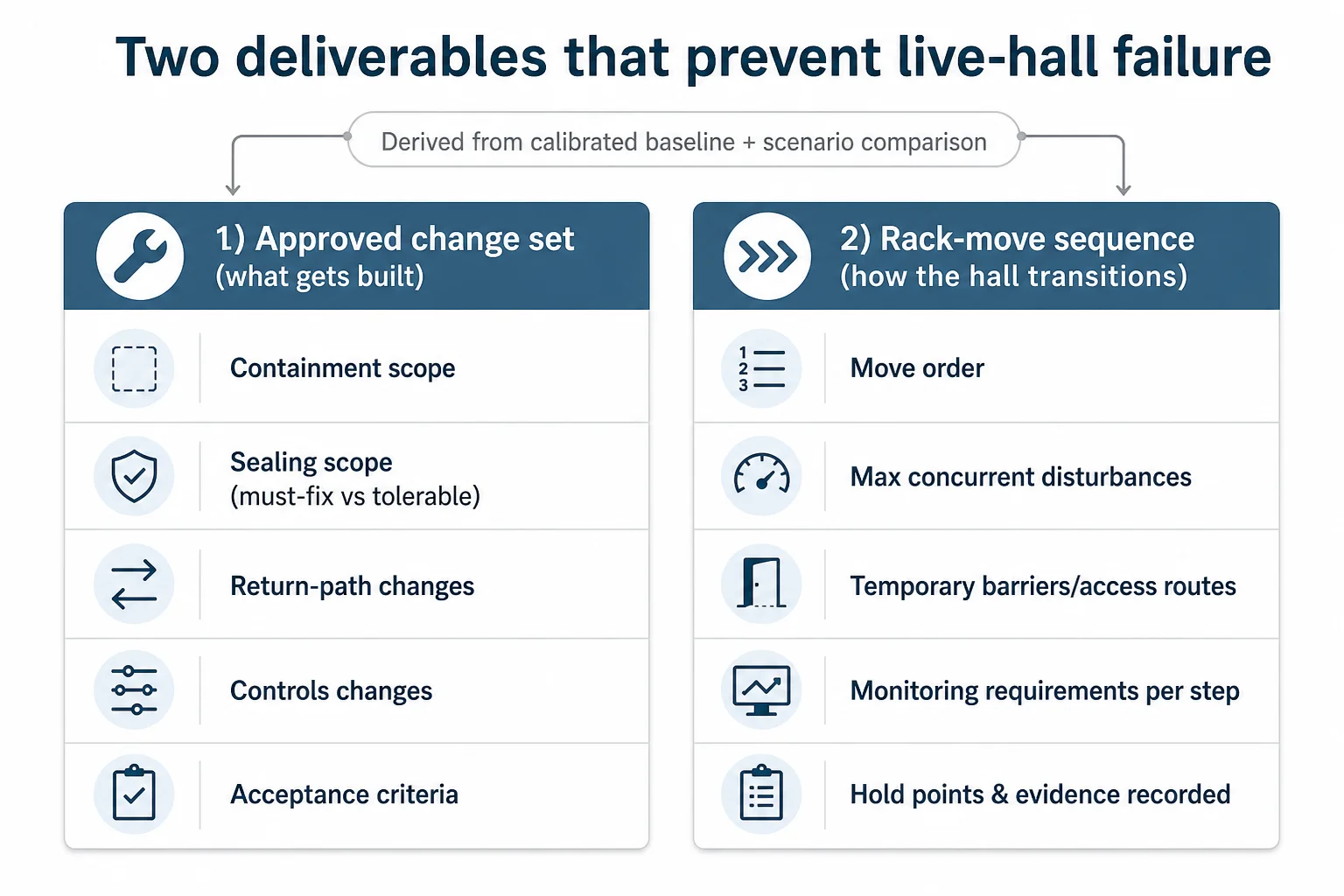
Output 1: the approved change set (what gets built and changed)
- Containment scope: panels/doors/roof, end-of-row closures, and interfaces to existing infrastructure (cable pathways, lighting, detection/suppression interfaces as applicable).
- Sealing scope: explicit list of leakage paths to be addressed (raised-floor openings, cable cutouts, rack top gaps, unused tiles), including what is “must fix” vs “tolerable” based on sensitivity cases.
- Return-path changes: any ducting, plenum separation, or return-air management works required to prevent short-circuiting and mixing.
- Controls changes: CRAH fan control strategy, supply temperature setpoints, alarms, and any required BMS integration or trending changes to verify performance.
- Operational constraints: what must remain true for the retrofit to be safe (e.g., which CRAHs must stay in service during transition, what temporary barriers are required, what access routes must remain clear).
- Acceptance criteria: what will be measured post-change, where, and what constitutes pass/fail.
Output 2: the rack-move sequence (how the hall transitions safely)
The rack-move sequence is a separate output because the hall passes through transient states that are not captured by a single “before vs after” model. The sequence defines the order of moves, the maximum allowed concurrent disturbances, and the monitoring requirements during each step so inlet conditions remain within the agreed envelope. This is also where commissioning vocabulary belongs at handover: the sequence should specify what is checked, when it is checked, and what evidence is recorded before proceeding to the next stage.
Post-retrofit verification: closing the loop without over-claiming containment’s incremental impact
Verification is not a victory lap; it is the control that prevents a retrofit from becoming a story rather than a result. The post-change measurement plan should mirror the baseline: rack inlet temperatures at credible intake locations, CRAH states, supply and return temperatures, pressure indicators where used, and any tile/grille delivery checks needed to confirm the airflow balance has not shifted into a fragile regime.
What to verify against the model (and what not to claim)
- Verify predicted patterns: recirculation hotspots, bypass pathways, and row-to-row imbalance are often the highest-value checks, not just average temperatures.
- Verify under representative states: include at least one credible maintenance mode (e.g., a CRAH out of service) if that was part of the scenario set used to approve the change.
- Verify monitoring coverage: ensure the hall instrumentation actually detects the failure modes the retrofit was designed to avoid (local intake excursions, not only room averages).
- Avoid attributing a clean incremental result to HAC alone: published field evidence typically bundles containment with sealing, return-path, and controls changes. Report the result as the outcome of the approved change set unless a controlled isolation exists.
This limitation is important enough to state plainly: there is strong field precedent that bundled airflow-management retrofits in live halls can improve usable cooling capacity and reduce fan energy (as in the LBNL/DOE legacy-facility case), but there is not equally strong published field evidence that isolates the incremental energy result of installing hot-aisle containment while holding leakage sealing, fan controls, return configuration, supply temperature, and IT layout constant. For that reason, post-retrofit reporting should focus on whether the hall now meets the intended inlet envelope and operational robustness, not on claiming a universal percentage saving from containment alone.
Hybrid-with-containment: rear-door and in-rack liquid-to-air in retrofit halls
Hybrid-with-containment is often treated as a transitional compromise, but it is an active design space. Rear-door heat exchangers (RDHx) and in-rack liquid-to-air approaches can reduce the air-side burden while keeping the hall largely air-managed. The key discipline is to avoid turning product ratings into an “industry envelope”: rear-door capacity depends on water temperature and flow, heat-exchanger geometry, server airflow, and what fraction of rack heat the door is intended to remove. Without a named model and stated design conditions, a generic RDHx rack-kW band is just a repeated rule of thumb.
Ongoing standardisation work reinforces that the category is live. The Open Compute Project has an active Door Heat Exchanger effort around ORV3 interfaces, working through fluid compatibility, leak, corrosion, reliability, and mixed-system issues. ASHRAE’s 2021 liquid-cooling white paper describes liquid-to-air heat exchangers in or near racks as an interim bridge where operators want liquid-cooled IT but facility water has not yet reached the racks. Separately, mixed air/liquid facilities are treated as a durable reality in current AI-era frameworks; the broader mixed-technology facility framing is usually handled as part of whole-hall retrofit strategy rather than a containment-only change.
CDU weight and access: a practical constraint, not a generic rule
For retrofit planning, CDU wet weight and clearance can be a real constraint on access routes and local floor loading, but it is not a single number. Delta’s GoCool-3000 (rated to 3,000 kW) specifies 2,800 kg with coolant (2,222 kg without), with a 1.2 m × 1.5 m plan footprint and stated service clearances of 1.2 m front and 0.8 m rear—so “a large CDU can weigh around three tonnes when filled” is defensible for that product class. The generalisation “CDUs weigh three tonnes” is not: Vertiv’s CoolChip documentation lists wet weights of approximately 550 kg at 600 kW, 1,086 kg at 1.35 MW, and 1,793 kg at 2.3 MW. These are vendor specifications—useful as primary product data, weak as evidence of what is typical—which is exactly why a generic floor-loading figure is unsuitable.
Beyond weight, practical constraints on bringing liquid into existing white space are supported in kind: piping and connection interfaces, coolant chemistry and material compatibility, filtration, leak management philosophy, maintenance access, and redundancy strategy. These constraints should be treated as retrofit design inputs alongside containment leakage control and return-path management.
Need to de-risk a live-hall containment change?
Azura supports operators with measurement plans, calibrated modelling, and scenario comparison so retrofit decisions are based on evidence, not rules of thumb.
Conclusion
A hot aisle containment retrofit in a live hall is defensible when it is treated as a verification problem, not a hardware problem. There is no standards-defined rack-kW ceiling for air cooling, and operator opinions on when liquid becomes necessary are widely split—so the right question is whether this specific hall can deliver the required inlet envelope robustly after the change. In that framing, Azura’s independent data center consulting services add value by turning measurements and scenario comparisons into a decision record the operator can defend—what was measured, what was modelled, which failure modes were tested, and what will be verified after installation.
The workflow that stands up is consistent: measure a baseline, calibrate the model to measurement (not to assumptions), compare scenarios that include rack positions and maintenance states, approve a change set, execute with a defined rack-move sequence, and then verify against predictions. Where published evidence does not isolate containment’s incremental benefit, the retrofit still succeeds by proving the outcome that matters: stable inlet conditions with reduced hotspot risk and a hall that is operable, not fragile.
Prove the retrofit before racks move.
If containment is already decided and the remaining risk is operational stability, Azura can help structure the baseline, calibration, and verification plan for a defensible change set.
References
- Global Data Center Survey 2025 — Uptime Institute (2025-06-01)
- Cooling Systems Survey 2025 — Uptime Institute (2025-10-01)
- State of the Data Center 2026 — AFCOM (2026-02-01)
- Best Practices Guide for Energy — Efficient Data Center Design: Air Management — U.S. Department of Energy (2011-11-01)
- Open Compute Project (OCP) – Open Rack V3 (ORV3) Specification — Open Compute Project (2021-01-01)
- GoCool — 3000 Coolant Distribution Unit – Product Specifications — Delta Electronics (2024-01-01)
- CoolChip CDU – Product Data Sheets — Vertiv (2024-01-01)