

A technical reference on how flexibility, restraint design, and equipment loads are verified for district cooling distribution and internal chilled-water piping under combined loads.
Executive Summary
- Chilled water piping stress analysis is a combined-load problem: sustained (pressure, weight), thermal (operating and transient), and displacement-driven loads (settlement, equipment movement) interact and must be checked together.
- Distribution networks and internal plant/building piping fail in different ways: buried pipe is governed by soil restraint, settlement, and anchor strategy, while above-ground systems are governed by support behaviour, expansion management, and nozzle-load control.
- Temperature change is only one input; the difficult cases come from mode changes (start-up/shutdown, TES charge/discharge, seasonal setpoint shifts) where gradients and imposed displacements drive fatigue and restraint overload.
- A credible model starts with boundaries and interfaces: what is “rigid” (civil structures), what is flexible (pipe, joints), and where loads are allowed to pass (anchors, guides, equipment nozzles, ETS heat exchangers).
- Support and restraint design should be treated as part of the analysis output, not a drafting task: guide gaps, friction, spring can selection, and anchor stiffness materially change calculated stresses and nozzle loads.
- The fastest route to rework is mismatched assumptions between stress, civil, and piping layout (e.g., unmodelled settlement, incorrect soil parameters, or assuming ‘free’ expansion at a penetration that is actually clamped).
- For district cooling piping design, stress deliverables that stand up in construction include: load cases and combinations, restraint schedule, support drawings with gaps and settings, nozzle-load reports, and a clear list of field tolerances and critical hold points.
Why chilled-water stress analysis is a live issue in district networks
Chilled-water piping is mechanically unforgiving when it is long, restrained, and connected to sensitive equipment. Modern district cooling networks also operate in more modes than a simple “on at design flow” assumption: partial-load seasons, staged plant, thermal energy storage (TES) charge/discharge, and frequent start/stop sequences all change temperature, flow, and boundary conditions. Those changes translate into displacement cycles and restraint loads that are easy to miss if stress work is reduced to a single steady-state expansion check.
This technical reference is written for engineers and reviewers who already understand piping layout and hydraulics, and need a practical, defensible method for chilled water piping stress analysis across two domains: (1) buried distribution networks and (2) above-ground internal piping in plants, ETS rooms, and buildings. It focuses on load definition, modelling choices, restraint/support behaviour, and acceptance checks (stress, displacement, and equipment nozzle loads).
For broader context on district network architecture and interfaces, see Azura’s pillar on District Cooling. This article goes deeper on the mechanical integrity layer that sits underneath district cooling piping design and chilled water pipe flexibility analysis.
What “stress analysis” covers for chilled-water systems (and what it does not)
In this context, “stress analysis” means verifying the mechanical behaviour of the piping system under defined load cases and combinations, and producing design outputs that can be built and operated. The analysis is only as good as the boundary definition: what is connected, what moves, what is restrained, and what loads are allowed to pass.
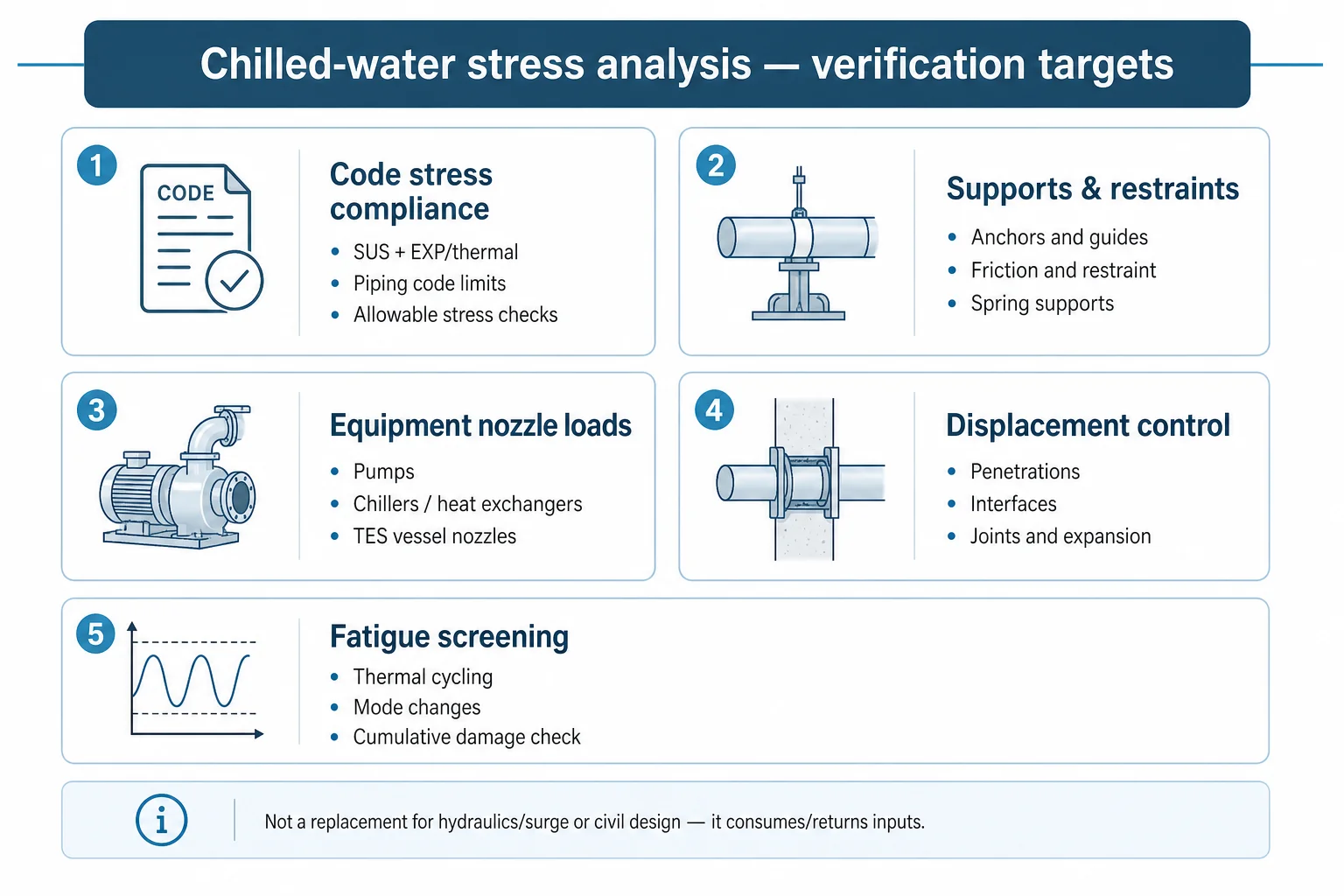
Typical verification targets
- Code compliance for stresses in pipe, fittings, and branches under sustained and displacement-driven loads (e.g., ASME B31.3 / B31.1 depending on project basis of design).
- Support and restraint adequacy: anchor loads, guide loads, friction effects, spring can sizing and travel, and structural interface loads.
- Equipment protection: nozzle loads and moments at pumps, chillers/heat exchangers, TES tank nozzles, and packaged skids; plus casing alignment implications where relevant.
- Displacement control: predicted movements at penetrations, expansion joints (if used), flexible connectors, and building interfaces.
- Fatigue risk screening where thermal cycling or mode changes drive repeated displacement ranges (TES charge/discharge is a common driver).
What it does not replace
- Hydraulic design (flows, ΔP, pump selection) and surge/water hammer analysis — those are separate disciplines, though their scenarios can create occasional load cases.
- Thermal/hydraulic behaviour inside TES tanks — see thermal energy storage diffuser design and CFD verification — mechanical interface loads at the tank nozzles matter here, but internal TES behaviour is a separate topic.
- Civil/structural design — but stress analysis must consume civil inputs (settlement, stiffness, penetration details) and return loads back to civil/structural.
Load cases that actually govern chilled-water networks
A practical load set for chilled-water systems needs to reflect how the system is built and operated, not only the design-point datasheet. The common miss is treating buried pipe as “fixed” and above-ground pipe as “free to expand”; in real projects both are partially restrained, and friction and stiffness decide where the load goes.
Sustained loads (always present)
- Pipe self-weight, insulation, and any trace heating or jacketing where used.
- Fluid weight for operating, hydrotest, and drained conditions (draining can be a separate sustained case if supports are sensitive).
- Internal pressure, including pressure thrust at changes in direction if the system includes expansion joints or flexible couplings that do not self-contain thrust.
Thermal and operational displacement loads
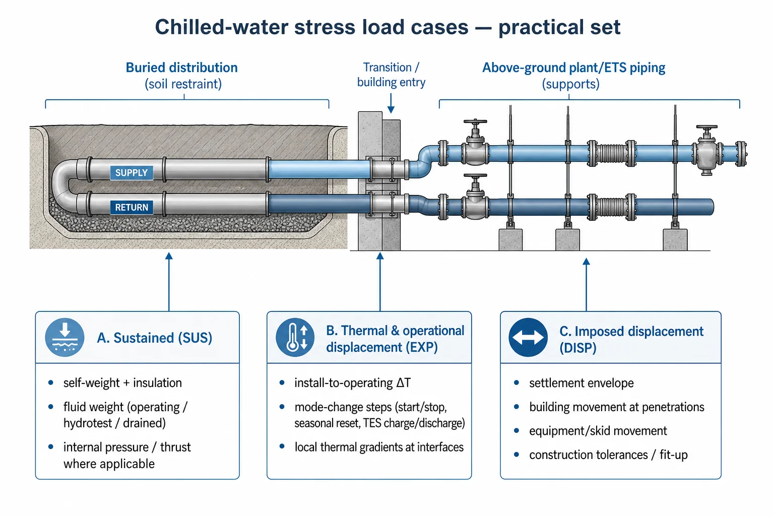
- Operating temperature change from installation condition to normal operation (including realistic construction temperature, not an arbitrary 20°C).
- Mode-change temperature steps: start-up/shutdown, seasonal supply temperature reset, and TES charge/discharge transitions where return temperatures can swing.
- Thermal gradients at interfaces (e.g., plantroom headers, ETS heat exchanger connections, and TES nozzles) which can create local bending demand even when bulk ΔT is modest.
Imposed displacements (the ‘civil’ loads that drive rework)
- Ground settlement along buried routes, including differential settlement at road crossings, utility corridors, and transitions into buildings or pits.
- Building movement at penetrations (thermal/structural movement joints) and relative movement between adjacent structures.
- Equipment movement: pump skid movement under thermal growth, heat exchanger differential movement, and allowable movements from vendor data where provided.
- Construction tolerance cases: misalignment at tie-ins, spool fit-up forces, and ‘as-built’ support elevation deviations that can pre-load the system.
Modelling approach: defining boundaries, restraint behaviour, and interfaces
The value of a stress model is not the colour plot; it is the traceability of assumptions. For district cooling networks, interfaces dominate: buried-to-above-ground transitions, ETS connections, and plant headers often govern more than long straight runs.
A defensible modelling sequence
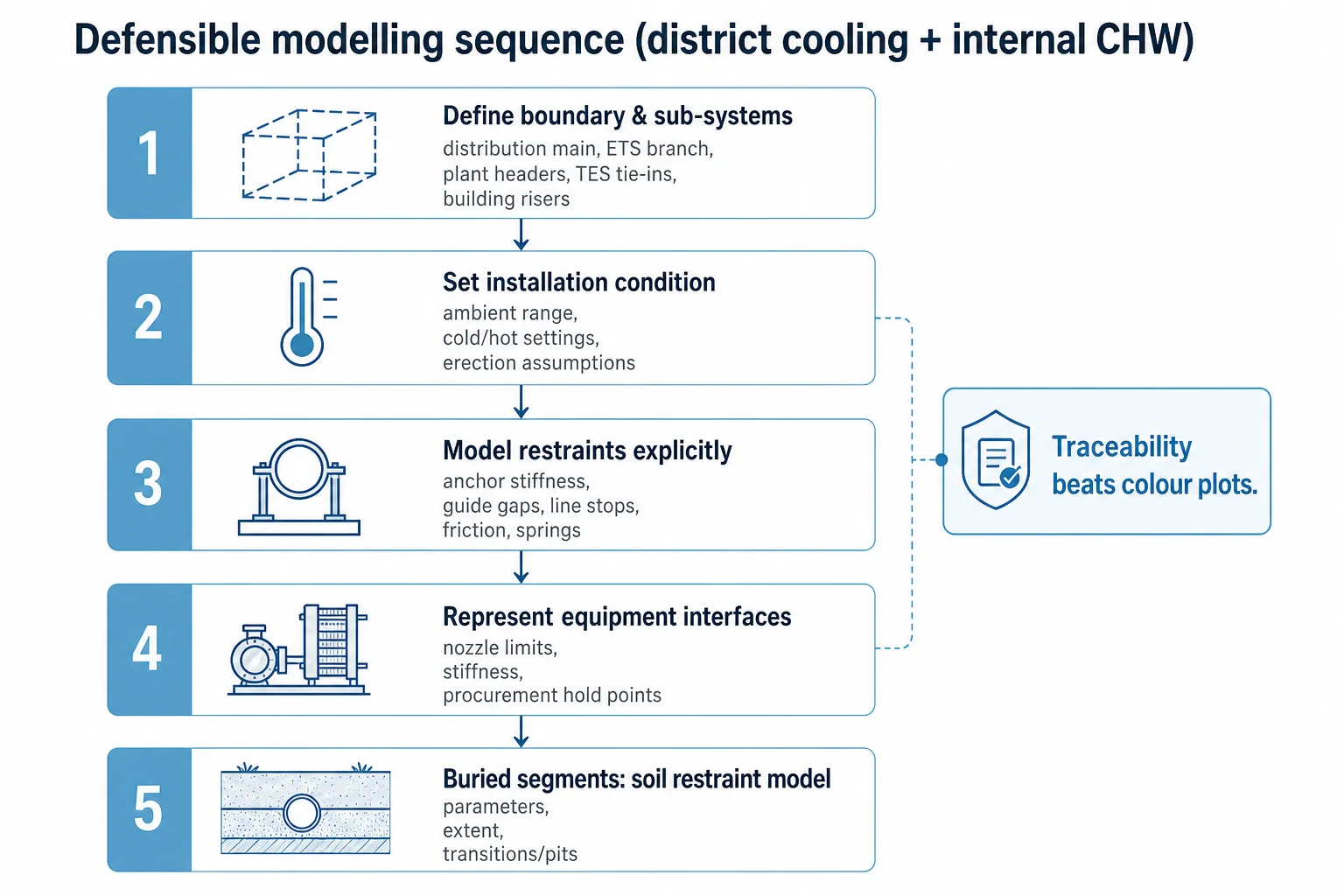
- Define the system boundary and split the model into logical sub-systems: distribution main, branch to ETS, plantroom headers, TES tie-ins, and internal building risers/branches. Each sub-system should have clear tie-in points and assumed stiffness.
- Establish the installation condition: ambient temperature range during construction, support settings (cold vs hot), and whether the system is erected ‘in the air’ before final supports are locked.
- Model restraint behaviour explicitly: anchor stiffness (not always infinite), guide gaps, line stops, friction coefficients, and spring support characteristics. Treat ‘guide’ as a directional restraint with a real gap, not a generic node constraint.
- Represent equipment connections with appropriate stiffness and allowable nozzle loads. Where vendor data is not available, use conservative assumptions and flag them as procurement hold points.
- For buried segments, define soil model parameters and the extent of soil restraint. Avoid treating the entire buried run as fully fixed unless justified; transitions and pits frequently behave differently.
Where specialised tools are used (e.g., CAESAR II or ROHR2), the engineering judgement sits in these inputs. The software will always produce numbers; the question is whether the restraint and boundary assumptions reflect the project reality. Azura’s broader capability context for stress and related analyses is outlined on Specialized Engineering Services.
Distribution networks: buried pipe, soil restraint, and settlement-driven stress
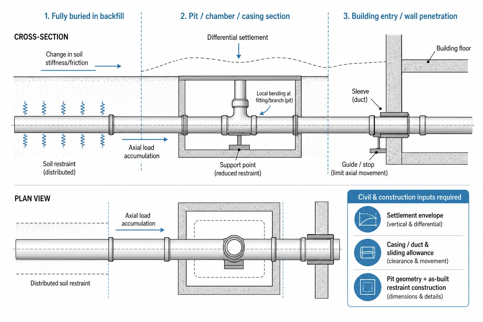
For district cooling piping design, the buried network is often assumed to be “stable” because it is supported continuously by soil. That assumption breaks down at discontinuities: pits, chambers, road crossings, casing pipes, building entries, and any location where soil restraint changes or the pipe is locally de-bonded.
What typically governs in buried chilled-water systems
- Differential settlement and imposed displacement at transitions (buried-to-above-ground, pits, and building penetrations).
- Anchor and restraint strategy: where axial loads are allowed to accumulate and where they are released; poor anchor placement can push loads into ETS/plant interfaces.
- Soil restraint assumptions: stiffness and friction vary with backfill, compaction, moisture, and whether the pipe is in a duct or casing.
- Local bending at fittings and branches in constrained pits where geometry changes but movement is restrained.
Inputs that must come from civil and construction
- Settlement envelopes and where differential movement is expected (including adjacent utilities and road construction).
- Details of casing/duct sections, insulation systems, and whether the pipe is allowed to slide relative to casing.
- Chamber/pit geometry and how supports/restraints are actually constructed (clamped, guided, or simply resting).
Network-level stress assumptions should align with the overall district cooling system concept and phasing. The existing overview pages on District Cooling Systems Design and District Energy Solutions cover the broader system context; this article focuses on how those network decisions translate into mechanical restraint and interface loads.
Internal piping: plantrooms, ETS interfaces, and nozzle-load control
Internal chilled-water piping is usually where stress problems become visible: movement at penetrations, vibration or support chatter, leaking flanges after thermal cycles, and equipment alignment issues. These are frequently traced back to restraint behaviour that was assumed rather than specified.
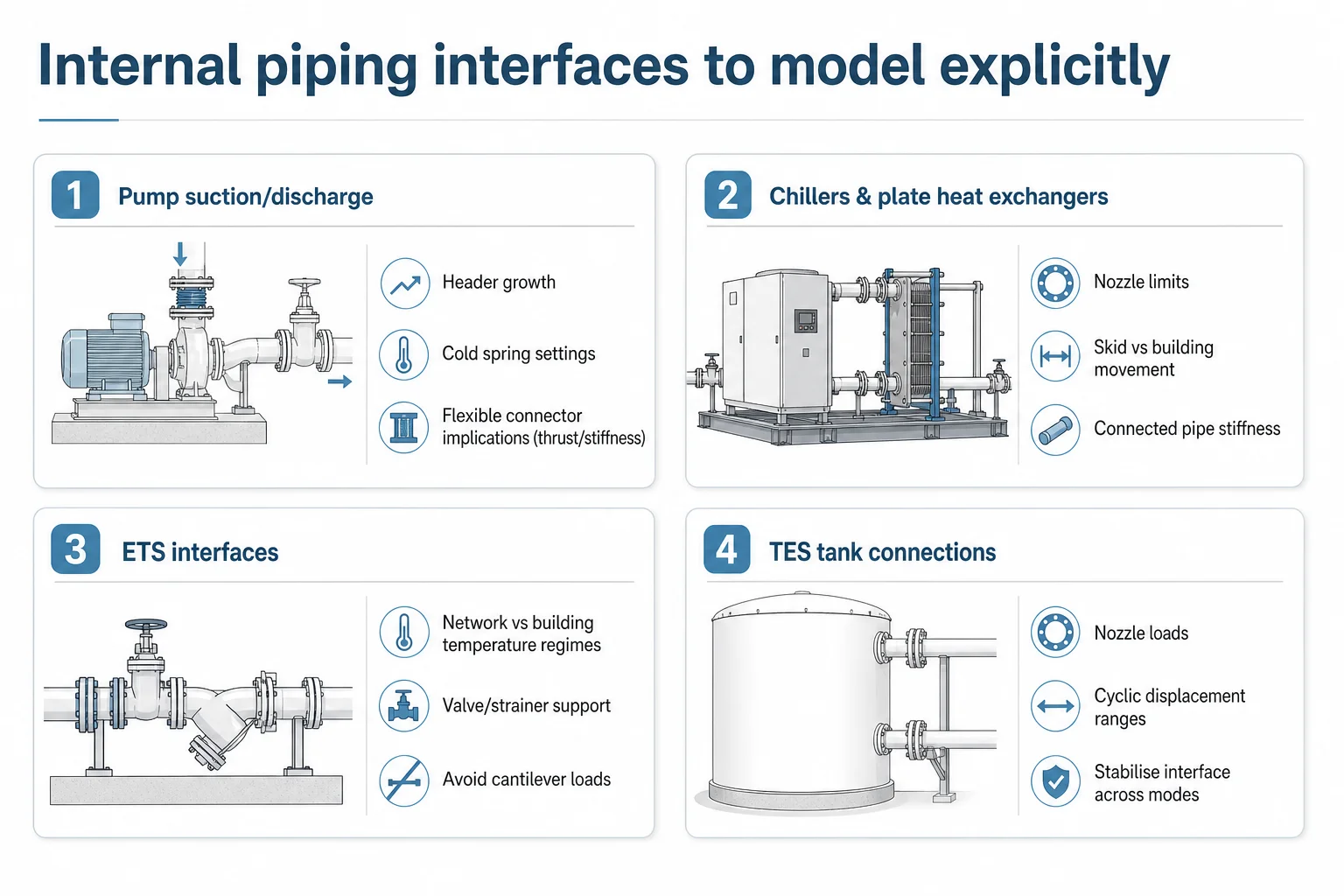
Interfaces that deserve explicit modelling attention
- Pump suction/discharge: thermal growth of headers, cold spring settings, and whether flexible connectors are used (and what they do to thrust and stiffness).
- Chillers and plate heat exchangers: nozzle load limits, differential movement between skid and building structure, and the stiffness of connected pipework.
- Energy Transfer Stations (ETS): building-side vs network-side temperature regimes, and how isolation valves and strainers are supported to avoid cantilever loads.
- TES tank connections: nozzle loads and cyclic displacement ranges during charge/discharge; keep the mechanical interface stable even when operating modes change; the in-tank hydraulic behaviour is covered under diffuser design and CFD verification.
Common failure modes when analysis is incomplete
- Overstressed fittings and branch connections due to unaccounted imposed displacement at penetrations or skids.
- Support failures or cracked anchors where friction or guide gaps were not specified and the system ‘locked up’ during temperature change.
- Excessive nozzle loads causing gasket leakage, exchanger plate pack issues, or pump casing distortion and misalignment.
- Fatigue at small-bore connections (vents, drains, instrument take-offs) when thermal cycling is frequent.
Thermal cycling and operating modes: where chilled-water systems pick up fatigue risk
The fatigue question in chilled-water systems is rarely about high stress intensity; it is about repeated displacement ranges at the same geometric discontinuities. A system that is fine in one steady-state case can still crack over time if it cycles daily and the restraint layout concentrates movement into a few locations.
Turning operating modes into stress cases
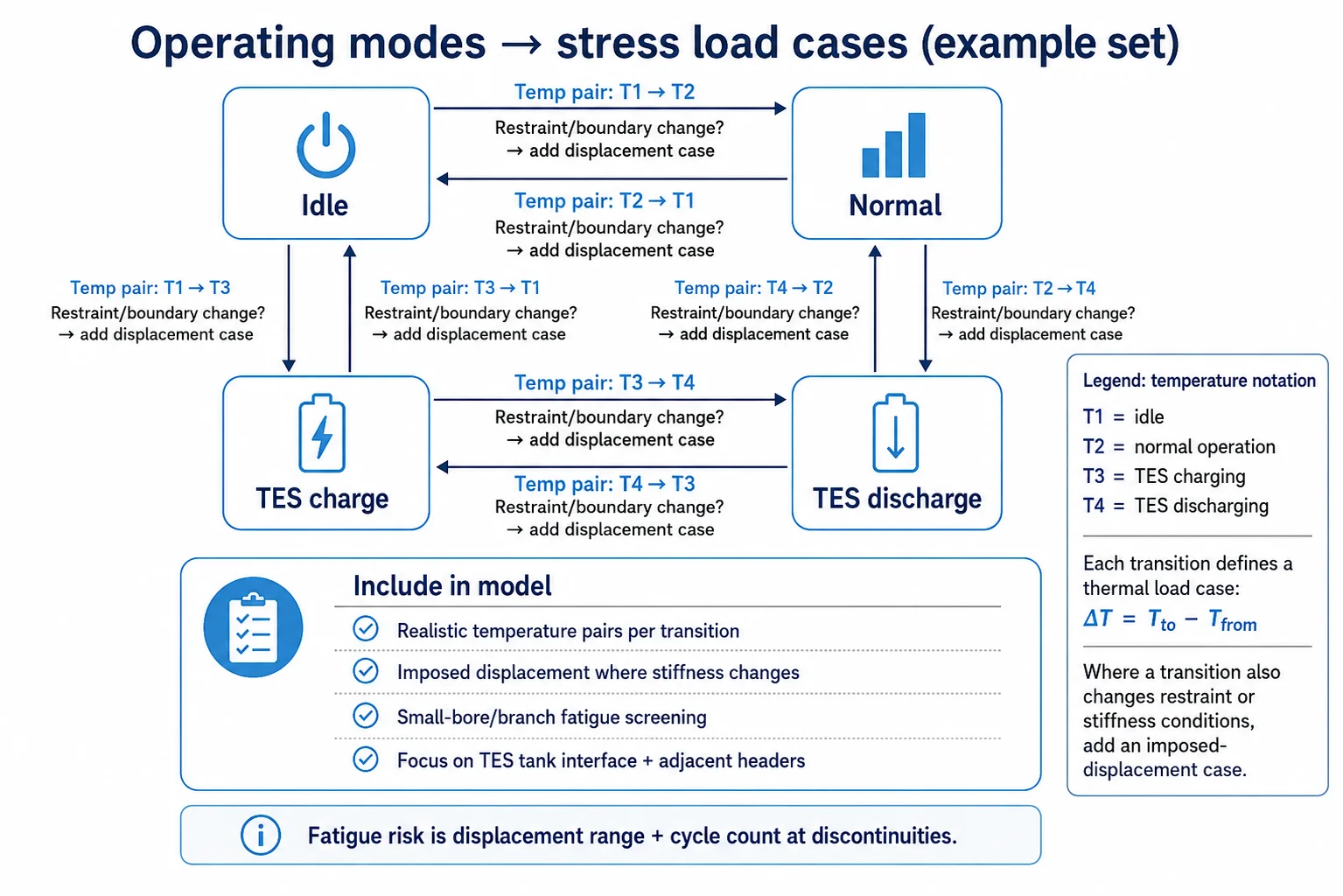
- Define realistic temperature pairs for each mode transition (e.g., ‘idle’ to ‘normal’, ‘normal’ to ‘TES discharge’), not only min/max design temperatures.
- Include imposed displacement cases where the mode change also changes boundary stiffness (e.g., valves opening/closing changing which headers see flow and temperature).
- Screen small-bore and branch connections for displacement-driven fatigue where cycling frequency is high.
- Where TES is present, focus on the tank interface and adjacent headers: charge/discharge can create local temperature swings even if the network supply temperature is stable.
Where projects also have stringent reliability requirements (for example, continuous cooling expectations in mission-critical facilities), operating modes can be more dynamic than typical comfort cooling. The underlying mindset is similar to resilience-driven design discussed in Datacenter Tier Classification, even though the application domain differs.
Decision Framework: a stress-analysis checklist that survives design → construction → operation
1) Define the boundary and interfaces
- List all equipment and structural interfaces (pumps, exchangers, TES nozzles, building penetrations, buried-to-above-ground transitions).
- For each interface, define: stiffness assumption, allowable movements, and allowable loads (or procurement hold point if unknown).
2) Build the load case set from reality
- Sustained: weight (operating, hydrotest, drained), pressure, insulation.
- Thermal: installation-to-operating, plus mode transitions (start/stop, seasonal reset, TES charge/discharge).
- Imposed displacement: settlement envelopes, building movements, skid movements, construction tolerances.
- Occasional: seismic/wind where applicable, relief events and surge scenarios where they create meaningful mechanical loads.
3) Model restraints as they are built
- Anchors: stiffness and load path to structure; avoid ‘infinite’ anchors without structural confirmation.
- Guides/line stops: specify gaps and directions; include friction and sliding surfaces where relevant.
- Springs: select based on operating load and travel; document cold/hot settings and field adjustment requirements.
4) Close the loop with deliverables and hold points
- Restraint/support schedule with loads and directions; support drawings that include gaps and settings.
- Nozzle-load report per equipment item, with assumptions clearly stated.
- Penetration movement report (predicted movement and required clearances).
- Construction hold points: ‘do not grout’ until alignment checked; ‘do not final-tighten’ until hot/cold condition verified; ‘as-built’ support elevations verified before hydrotest.
Need a stress model that matches site reality?
Azura supports chilled-water networks and plant/building piping with flexibility analysis, restraint design, and equipment nozzle-load verification for district cooling projects.
Where this work matters most on district cooling projects
In delivery, the highest-risk moments are predictable: first tie-ins between buried mains and plant/ETS rooms, first thermal cycles after commissioning, and any later network expansion that changes boundary conditions. Stress work that is disconnected from civil settlement assumptions, penetration details, or equipment procurement data tends to reappear as site queries and retrofit restraints.
- Concept and route-stage input: identifying where anchors, chambers, and transition details will be needed before the route is fixed.
- Detailed modelling and flexibility analysis (CAESAR II / ROHR2 workflows) with explicit restraint behaviour and settlement envelopes.
- Support and restraint design outputs that are buildable: gaps, settings, and structural load hand-offs.
- Equipment interface verification: nozzle loads at pumps, heat exchangers, and TES connections, with procurement hold points where vendor limits are required.
This sits alongside Azura’s broader district energy engineering work and the specialist analysis capability described on Specialized Engineering Services, and complements district cooling system design activities covered on District Cooling Systems Design.
Conclusion
Chilled water piping stress analysis is often treated as a narrow thermal-expansion check, but district networks and internal plant/building piping are governed by combined loads: sustained weight and pressure, imposed displacements from settlement and equipment movement, and mode-driven thermal cycling. The engineering task is to define boundaries and restraint behaviour realistically, then verify stresses, displacements, and nozzle loads against explicit acceptance criteria.
Projects that avoid late-stage restraint rework are the ones that treat supports and anchors as part of the analysis output, align civil and MEP assumptions early, and translate operating modes (including TES transitions) into load cases. When that discipline is applied, the stress package becomes a construction and operations tool—not just a calculation report.
Reduce restraint rework and interface failures.
For district cooling and internal chilled-water systems where settlement, cycling, or equipment loads are material, Azura can provide stress analysis and coordinated support design aligned to delivery constraints.
References
- ASME B31.3 — Process Piping — ASME (2024-01-01)
- ASME B31.1 — Power Piping — ASME (2024-01-01)
- EN 13941 — 1:2019 — District heating pipes — Design and installation of thermal insulated bonded pipe systems for directly buried networks — CEN / BSI (2019-09-25)
- District Cooling Best Practice Guide — International District Energy Association (IDEA) (2020-01-01)
- CAESAR II — Product Overview and Technical Resources — Hexagon (2025-01-01)