


Both topologies can work; the deciding factor is usually the return-air path and operational constraints, not a generic “hot is better” claim.
Executive Summary
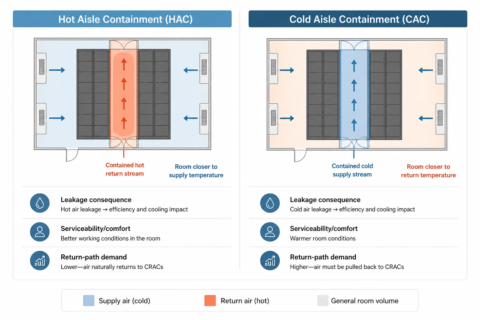
- Hot aisle containment (HAC) and cold aisle containment (CAC) primarily change where the uncontrolled air volume sits: HAC keeps the room near supply temperature while containing hot return; CAC keeps the room near return temperature while containing the cold supply.
- The best-known measured comparison (Intel/T-Systems DataCenter 2020, 2011) tested roughly 5.5–22 kW/rack at ~22°C inlet and found the efficiency difference between HAC and CAC small once airflow management was optimised; it did not generalise to today’s 50–120+ kW AI racks.
- Vendor modelling (Schneider Electric/APC) is often quoted as ~43% lower annual cooling energy and ~15% annualised PUE improvement for HAC vs CAC; those are model outputs under specific assumptions, not independent field replication.
- For most conventional, air-cooled halls, the first-order constraint is the return-air path: whether hot return can be captured and delivered back to CRAH/CRAC intakes via a plenum/ducted route without creating bypass, short-circuiting, or maintainability issues.
- Measured evidence separates the two most clearly under outage/ride-through: at ~17.5 kW/rack in the Intel/T-Systems tests, CAC showed a small ride-through advantage attributed to the larger cold-room air volume.
- Heat reuse is helped by higher, steadier return temperatures (less bypass/recirculation), but air-side waste heat is typically ~25–35°C and usually still needs a heat pump to meet district-heating temperatures; there is no strong evidence that HAC uniquely outperforms a well-executed CAC with a well-designed return path.
- EU and Dutch obligations are moving beyond “reporting only”: Directive (EU) 2023/1791 introduces conditional waste-heat provisions above 1 MW total rated energy input, Delegated Regulation (EU) 2024/1364 standardises reporting (including average waste-heat temperature and Energy Reuse Factor), and Dutch RVO requires annual reporting above 500 kW installed IT power.
What this comparison is really deciding (and what it is not)
The phrase “hot aisle containment vs cold aisle containment” is usually treated as a binary pros-and-cons list. In practice it is a selection decision for a specific room: where the uncontrolled air volume sits, how return air gets back to the cooling units, and what happens during abnormal conditions such as fan failures or power transfers.
Scope matters. This comparison sits inside the conventional and colocation, air-cooled envelope where containment is a realistic primary lever. High-density AI halls that are predominantly liquid-cooled are a different topology conversation; mixed air/liquid halls are increasingly durable, but the whole-hall conversion question is a separate retrofit problem.
The option set is also wider than the binary. Fan walls matter because they change the return-air path (the central deciding constraint). CDUs and liquid cooling can coexist with contained air-cooled zones in mixed halls; they are named here only to avoid false binaries, not to develop their sizing, weights, or density bands.
The core physical difference: what temperature the room sits at
A useful way to think about the two topologies is: HAC tends to keep the general room volume closer to supply temperature while containing the hot return stream; CAC tends to keep the general room volume closer to return temperature while containing the cold supply stream. That single difference drives many of the practical trade-offs around serviceability, comfort, leakage consequences, and what happens when containment integrity degrades.
What the two topologies change in the room (and why fan walls belong in the option set)
Cold aisle containment (CAC): contain the supply, let the room be “warm”
In CAC, the cold aisle is enclosed so that supply air is delivered to server inlets with minimal mixing. The rest of the room becomes the return-air volume. This can simplify some retrofit geometries because the containment is local to the aisle ends and overhead, but it also means the general room is warmer and the return stream is more exposed to bypass paths and local recirculation if the return route is not well defined.
Hot aisle containment (HAC): contain the return, let the room be “cool”
In HAC, the hot aisle is enclosed so that server exhaust is captured and delivered back to the cooling units with minimal dilution. The general room stays closer to supply temperature, which can improve working conditions and reduce the chance that leaked air creates local hot spots at inlets. The engineering obligation moves to the return path: the hot stream has to be guided back to CRAH/CRAC intakes via a plenum or ducted return without short-circuiting back to supply.
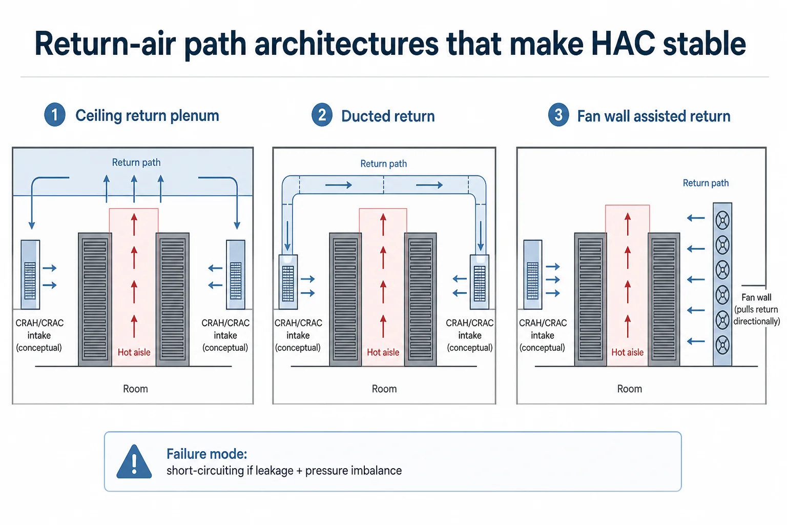
Fan walls as a return-path variable (not a third “containment type”)
Fan walls belong in a containment selection article because they can change the return-air path and the pressure relationships that decide whether return capture is stable. In rooms where ceiling height, obstructions, or legacy ductwork make a clean return plenum impractical, a fan wall can be a way to enforce return flow directionality and reduce the sensitivity to small leakage paths. That does not remove the need for containment discipline; it changes the mechanism by which return integrity is maintained.
CDUs and direct-to-chip liquid cooling are increasingly present even in predominantly air-cooled facilities, but the detailed mechanical integration (weights, floor loading, rack-side heat exchangers) is a different verification problem. Mixed air/liquid halls are also increasingly common; the whole-hall conversion question is a broader retrofit decision rather than an aisle-topology choice.
What published evidence actually settles (and what it does not)
Intel/T-Systems DataCenter 2020 (Munich lab, November 2011): the test conditions matter
A real, specific comparison exists: the Intel/T-Systems DataCenter 2020 work (published November 2011) reports testing in the T-Systems/Intel laboratory in Munich. The hot-versus-cold containment comparison covered rack loads of approximately 5.5 to 22 kW per rack, with nominal server inlet air around 22°C and chilled-water supply around 14°C in the principal comparison. Those conditions are the boundary of what the result can support.
The key conclusion was not that containment is irrelevant. It was that, after airflow management was optimised, the energy-efficiency difference between hot-aisle and cold-aisle containment was small enough to fall within practical measurement and site-specific variation. In other words: optimising the air path mattered more than the choice of which side of the aisle was enclosed.
The same programme is also cited for dramatic return-temperature improvements, but those improvements were observed during an earlier optimisation step that changed multiple variables together. In that step, sealing leakage and implementing cold-aisle containment coincided with CRAH return temperature moving from about 24°C to 38°C, CRAH temperature difference moving from roughly 6°C to 17°C, and fan speed moving from 100% to about 30%—while supply conditions were also changed. That makes it attributable to the documented work, but not a clean “containment alone” delta.
The one place the measured evidence separates HAC and CAC: outage ride-through
Under an outage scenario at around 17.5 kW per rack, the Intel/T-Systems work reported a small ride-through advantage for cold-aisle containment, attributed to the larger volume of cold air available in the contained space. It also reported hot-aisle advantages under some lower-density outage conditions. The important point is that the difference emerged under transient/abnormal conditions rather than as a large steady-state efficiency gap.
The contested efficiency literature: three claims, three different evidential weights
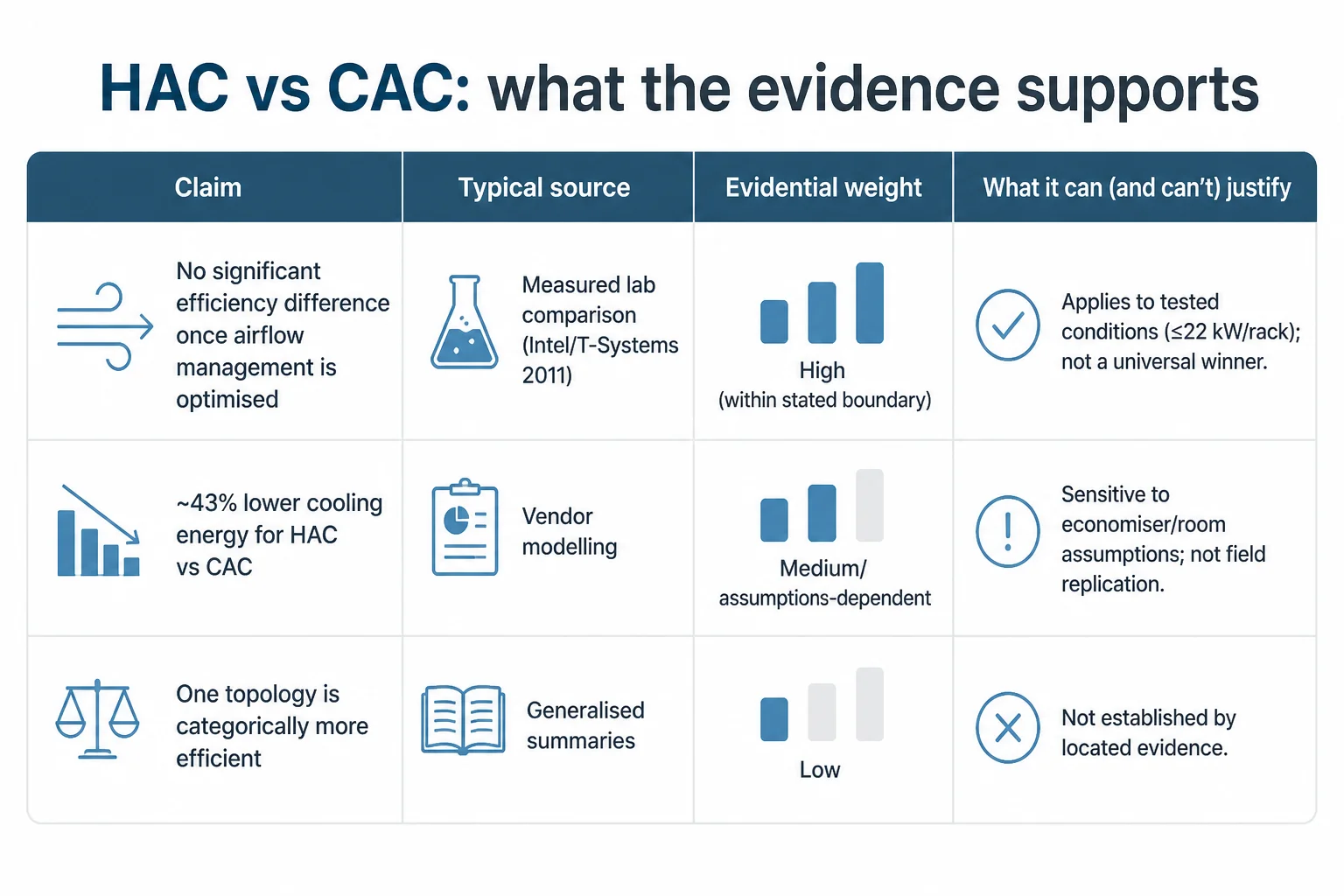
Schneider Electric/APC modelling has long reported materially greater energy savings for hot-aisle containment than cold-aisle containment under its modelled economiser and room assumptions. The figures are often quoted as approximately 43% lower annual cooling energy and a 15% annualised PUE improvement for hot-aisle containment versus cold-aisle containment. These are vendor model outputs under specific assumptions, and Schneider sells the relevant infrastructure; repetition in later papers does not turn modelling into independent field measurement.
- Claim 1: HAC and CAC have no significant efficiency difference once airflow management is optimised. This is supported by the Intel/T-Systems laboratory comparison at ≤22 kW/rack under the stated conditions.
- Claim 2: HAC reduces cooling energy by ~43% versus CAC. This is traceable to vendor modelling results, but is disputed as a general claim because it is assumption-dependent and not a field replication.
- Claim 3: one topology is categorically more efficient. This is not established by the located evidence; outcomes depend strongly on architecture and operating assumptions.
The defensible position is that the literature does not settle a universal winner. Anyone asserting a universal answer is either extrapolating a 2011 low-density lab result beyond its boundary, or treating vendor modelling as if it were general field evidence.
The deciding constraints (start with the return-air path)
Constraint 1 — Return-air path integrity (plenum vs ducted return, height, obstructions)
The return-air path decides more than most “HAC vs CAC” summaries admit. Hot-aisle containment typically demands a contained, credible route from the hot aisle to the cooling-unit intakes—often a ceiling return plenum or a ducted return system. If the room cannot provide that (insufficient ceiling height, heavy overhead services, fragmented ceiling zones, or return intakes that cannot be served without long, leaky paths), then HAC can become fragile: small leakage and pressure imbalances create short-circuiting and hot-spot risk.
Cold-aisle containment can be more tolerant of overhead obstructions because it is not trying to transport a contained hot stream across the room; it is trying to protect the cold supply at the point of delivery. That does not make it “better”—it makes it more feasible in some retrofit geometries. The trade is that the room becomes a warmer return volume and operational comfort and serviceability can be affected.
Constraint 2 — Supply temperature, density intent, and the real equipment envelope
ASHRAE’s current guidance for air-cooled equipment is often misrepresented as “the envelope has widened recently”. The recommended dry-bulb inlet range for A1–A4 remains 18–27°C. Allowable inlet bands are: A1 15–32°C, A2 10–35°C, A3 5–40°C, A4 5–45°C. Those A3/A4 maxima (40°C and 45°C) were already present in 2011 and were unchanged in 2015; the notable 2015 changes were mainly humidity-related, not a recommended temperature shift.
More importantly for higher-density air-cooled products, the Fifth Edition introduced class H1 with a narrower band: recommended 18–22°C and allowable 15–25°C. ASHRAE’s 2021 liquid-cooling white paper explains H1 exists because some high-density air-cooled products have more restrictive inlet requirements.
Vendor capability is also product- and configuration-specific. HPE’s current Gen12 environmental documentation supports A3 operation to 40°C and A4 to 45°C on many ProLiant models, but not universally: examples in HPE’s own tables include DL380a Gen12 without A4 support and DL384 Gen12 without either A3 or A4 extended-ambient support. A blanket statement that “modern servers tolerate 40–45°C” is therefore demonstrably wrong.
ASHRAE also reiterated in correspondence to the European Commission (January 2025) that 27°C is the recommended upper inlet temperature for ordinary A1–A4 operation, noted that some hyperscalers run beyond it, and emphasised that optimisation outside the normal envelope is a complex, multivariable engineering evaluation rather than a universal setpoint change.
Separately from standards evolution, the room behaviour still matters: as supply temperatures rise and density intent increases, CAC’s penalty of leaving the whole room at return temperature becomes more operationally and thermally consequential, while HAC keeps the room closer to supply temperature. That is a mechanism about where the warm air volume sits and how leakage manifests; it is not an ASHRAE-derived rule and it does not override the need to verify the full supply/return architecture.
Constraint 3 — Outage and ride-through posture
If ride-through during cooling interruptions is a key requirement, the measured comparison evidence that exists points to CAC having a small advantage at around 17.5 kW per rack under outage, attributed to the larger cold-air volume in the contained space. That does not make CAC universally preferable; it makes outage behaviour a constraint that has to be explicitly tested against the hall’s topology and control sequences.
Heat reuse: return temperature helps, but air-side heat still usually needs a heat pump
Why bypass air depresses return temperature (and why containment quality matters)
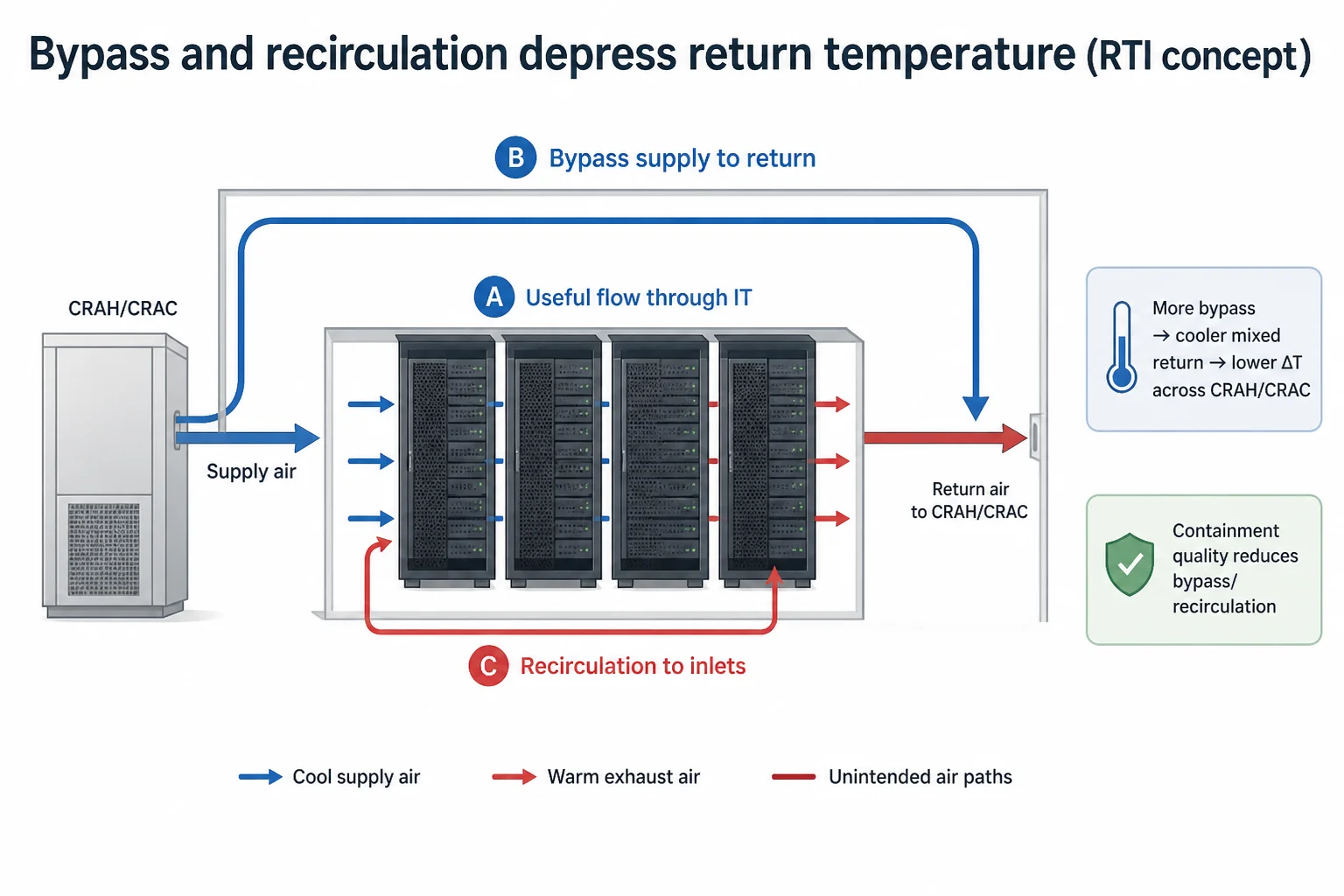
The engineering basis for “better airflow management raises return temperature” is straightforward. DOE’s Return Temperature Index (RTI) framework explains that bypass supply air depresses the air-handler return temperature because it reaches the return without passing through IT equipment. Reducing bypass and recirculation means more of the return stream represents actual server exhaust. This is an airflow-management effect; it does not, by itself, prove a unique advantage for hot-aisle over cold-aisle containment.
Typical temperatures and what district heating actually requires
A recent peer-reviewed review puts typical recoverable air-side data-centre heat around 25–35°C, compared with roughly 50–60°C for direct liquid cooling. Conventional district-heating networks generally require a heat pump to lift lower-temperature sources to network conditions; the value proposition is often about continuity and proximity, not that the source is already at network supply temperature.
Fourth-generation district-heating concepts run around 50–60°C supply and 25–35°C return, while many existing third-generation networks run substantially hotter. A cited Darmstadt case averaged roughly 88/58°C and still required a heat pump even with an approximately 45°C liquid-cooled HPC heat source. The International Energy Agency’s district-heating work reaches the same conclusion: heat pumps are a central enabling technology for upgrading low-temperature waste sources into existing networks.
Dutch practice illustrates the same pattern. RVO documents heat-reuse schemes using low-temperature local loops and heat pumps; in its Aalsmeer example, recipients are expected to use heat pumps to raise data-centre waste heat to delivery temperature, and other examples use aquifer thermal storage or local heat/cold exchange.
What containment does (and does not) buy you for heat reuse
A hotter, steadier return improves heat-recovery thermodynamics because it reduces the heat-pump lift required. It does not remove the heat pump as a requirement in most real district-heating integrations. A separate practical point is that segregating exhaust and maintaining return-path integrity makes heat-reuse interfaces easier to engineer and operate. At the same time, there is no strong primary evidence that hot-aisle containment uniquely outperforms a well-executed cold-aisle containment scheme paired with a well-designed return path; the heat-reuse outcome depends on the whole supply/return architecture and the external network conditions.
EU and Dutch regulatory context: thresholds, indicators, and why the regime is still evolving
Containment choices can become relevant to compliance and reporting because they affect measurable thermal behaviour (mixing, return temperature stability) and therefore the credibility of waste-heat characterisation. The regulatory driver is not “containment type” directly, but the ability to document energy and waste-heat performance transparently.
Directive (EU) 2023/1791: waste-heat provisions above 1 MW are conditional, not absolute
Directive (EU) 2023/1791 (the recast Energy Efficiency Directive) introduced data-centre provisions. Data centres with total rated energy input exceeding 1 MW fall within the waste-heat provisions: Member States are to ensure use of waste heat or other heat-recovery applications unless technical or economic infeasibility is demonstrated. For newly planned or substantially refurbished facilities, an installation-level cost-benefit assessment is relevant. The obligation is therefore conditional; it is not an unconditional requirement to connect every >1 MW data centre to district heating.
Delegated Regulation (EU) 2024/1364: common reporting and a rating framework
Commission Delegated Regulation (EU) 2024/1364 implements the common EU data-centre reporting and rating framework, including energy, water and waste-heat indicators. Commission guidance now includes average waste-heat temperature and calculates an Energy Reuse Factor from reported data, which increases the value of consistent measurement boundaries and stable operating behaviour. Where heat is upgraded for reuse, the heat pump placement (inside vs outside the declared data-centre boundary) can change reported PUE and ERF under ISO 30134.
The Netherlands: RVO reporting above 500 kW installed IT power
In the Netherlands, RVO states that owners/operators of data centres with at least 500 kW of installed IT power must report energy-efficiency information annually. The requirement was active again in 2026, and Dutch submissions feed the European database.
The regime is still developing. The European Commission is working on the next phase of the EU data-centre sustainability rating scheme and on minimum performance standards, using the first reporting cycles as evidence. Statements that EU rules amount only to “reporting” are now incomplete.
How the answer is settled for a specific hall (what to verify, not what to assume)
A containment topology decision should survive design review and operations handover. That requires turning “HAC vs CAC” into verifiable questions tied to the room’s geometry, the cooling unit arrangement, and the control sequences.
- Return-air path verification: is the intended return route a true plenum/ducted path with predictable pressure relationships, or a collection of leakage routes? Identify ceiling height constraints and overhead obstructions that will force discontinuities.
- Mixing and bypass risks: where can supply bypass directly to return without passing through IT, and where can return recirculate into inlets? Treat leakage as a stability risk at higher densities, not just an efficiency loss.
- Operating envelope check: align intended inlet and supply setpoints with ASHRAE recommended bands (A1–A4: 18–27°C recommended; H1: 18–22°C recommended) and with vendor configuration-specific limits (extended ambient is not universal).
- Outage and ride-through: explicitly model and test what happens during power transfers, fan failures, or cooling interruptions; the one measured comparison suggests CAC can have a small ride-through advantage at ~17.5 kW/rack under outage due to cold-air volume.
- Maintainability and serviceability: confirm that containment geometry does not make routine work unstable (panels removed, doors propped, temporary blockages) and that operational procedures match the chosen topology.
CFD can be a useful instrument to settle room-specific questions (recirculation mechanisms, bypass paths, and the effect of obstructions) when used to test targeted geometry changes rather than to generate plots. The detailed CFD methodology and validation expectations sit with containment-change verification work, not with this selection article.
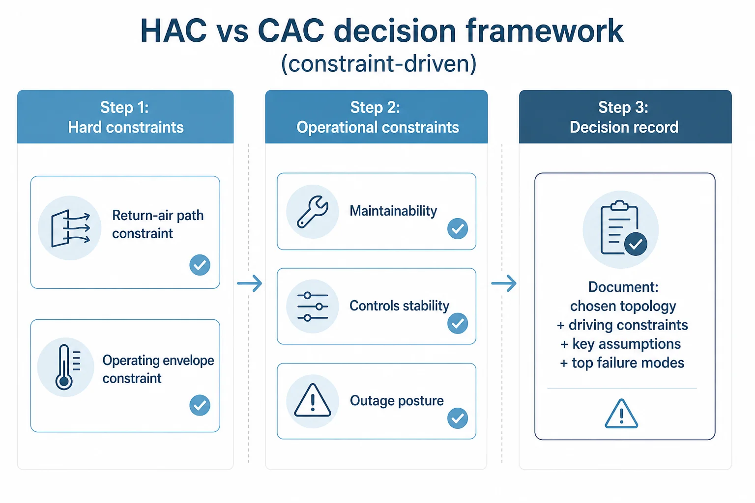
Decision framework: selecting containment by constraint (not by preference)
A containment decision becomes robust when it is structured as a constraint-driven selection rather than a preference-driven debate. The framework below is designed to produce a choice that can be defended in design review and then operated without surprises.
Step 1 — Eliminate infeasible options using hard constraints
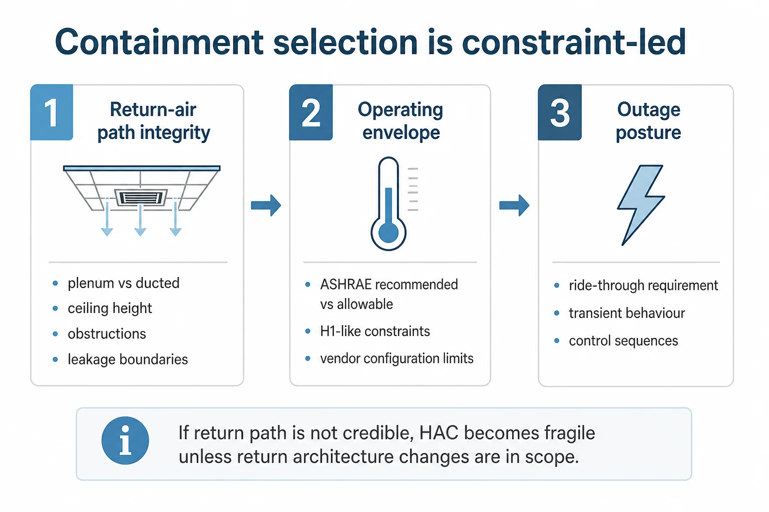
- Return-air path constraint: if the hall cannot provide a credible, contained return route (plenum or ducted) back to CRAH/CRAC intakes, treat HAC as high-risk unless fan-wall or return-architecture changes are in scope.
- Operating envelope constraint: if the target deployment includes high-density air-cooled products with restrictive inlet requirements (H1-like behaviour), treat “run hotter” as a hypothesis to validate against vendor configuration limits, not as a design default.
Step 2 — Compare the remaining options on operational constraints
- Maintainability: what happens to containment integrity during routine work (doors open, panels removed, temporary obstructions)?
- Controls stability: will the cooling control strategy still work when return air is concentrated (avoid control schemes that assume well-mixed room return)?
- Outage posture: is ride-through during interruptions a design requirement, and how does the topology behave under that transient condition?
Step 3 — Produce a hall-specific decision record
The output should be a short decision record: chosen topology, the constraints that drove the choice, the key assumptions (return path, setpoints, density intent), and the two or three failure modes that must be designed out or operationally controlled.
Containment choice blocked by return-path constraints?
Azura supports data centre owners and operators with containment selection studies, airflow-path assessment, and room-level verification planning for retrofit and new-build halls.
Where containment decisions go wrong in delivery
Containment decisions most often go wrong when the design assumes an ideal return path and ideal operational behaviour. In real rooms, small leakage routes, overhead obstructions, and maintenance practices (panels removed, doors left open) can turn a “works on paper” topology into a fragile one.
Engineering support on containment selection typically needs to tie together three threads: the physical return path (plenum/ducted feasibility and pressure relationships), the control strategy (what signals the cooling plant is actually using), and the operational model (service access, change control, and how excursions are handled). That kind of cross-discipline integration is typically delivered with Azura’s data center consulting services, spanning technical due-diligence, MEP integration, and support through implementation. Azura’s role in these studies is to structure the decision around those constraints and define what must be verified before a topology is treated as safe to scale.
Practical first moves before committing to HAC or CAC
- Draw the return-air path as a first-class system: from rack exhaust to CRAH/CRAC intake, including every ceiling zone, obstruction, and leakage boundary.
- Write down the intended inlet/setpoint policy and check it against ASHRAE recommended bands and vendor configuration-specific limits; do not assume extended-ambient support is universal.
- Decide whether outage ride-through is a requirement and, if it is, model the transient behaviour explicitly (the limited measured evidence suggests CAC can have a small advantage at ~17.5 kW/rack under outage due to cold-air volume).
- Treat containment integrity as an operational control problem as well as a design problem: define how panels/doors are managed during maintenance and how deviations are detected.
- If the hall geometry is complex, use CFD as a targeted verification tool to test the specific recirculation or bypass mechanisms the room is likely to produce, rather than as a generic “CFD report” deliverable.
Conclusion
Hot aisle containment and cold aisle containment are both viable approaches in conventional, air-cooled data centres. The published evidence that is often cited does not establish a universal efficiency winner: the best-known measured comparison (Intel/T-Systems, 2011) found little difference once airflow management was optimised, while vendor modelling that claims large HAC advantages is assumption-dependent and not a field replication.
A defensible choice is therefore made by constraint. Start with the return-air path and the hall geometry, then check the real operating envelope (ASHRAE recommended ranges, H1 constraints, and vendor configuration limits), and only then compare outage behaviour and operational maintainability. The result is a topology that fits the room you actually have, not the one the marketing diagram implies.
Make the decision defensible, not fashionable.
If HAC vs CAC is on the critical path for a live programme, Azura can help turn the choice into verifiable constraints: return-air path, operating envelope, outage posture, and operational maintainability.
References
- For Data Center Energy Efficiency, Hot — Aisle Beats Cold-Aisle Containment (modelling discussion) — Schneider Electric Blog (APC by Schneider Electric) (2011-09-13)
- Thermal Guidelines for Data Processing Environments (5th Edition) — Reference Card — ASHRAE Technical Committee 9.9 (2021-01-01)
- HPE ProLiant Servers — Environmental Specifications (Gen12) — Hewlett Packard Enterprise (2024-01-01)
- Air Management for Data Center Energy Efficiency: Return Temperature Index (RTI) — U.S. Department of Energy (2011-06-01)
- Directive (EU) 2023/1791 on energy efficiency (recast) — European Parliament and the Council of the European Union (2023-09-13)
- Commission Delegated Regulation (EU) 2024/1364 supplementing Directive (EU) 2023/1791 as regards a common Union scheme for rating the sustainability of data centres — European Commission (2024-06-14)
- Rapportageplicht energie-efficiëntie datacentra — Rijksdienst voor Ondernemend Nederland (RVO) (2026-01-01)