

A sequenced, engineering-first way to decide whether an operational data hall can carry a changed load—and what it takes to close the gaps without breaking live operations.
Samenvatting
- A data center retrofit is best treated as a sequence of feasibility gates—structure, power chain, then cooling deliverability—so teams do not spend design effort on a hall that fails a prior constraint.
- Rack-density headlines can mislead retrofit decisions: Uptime’s 2026 survey reports a modal rack-density average just above 11 kW, but when facilities above 30 kW are excluded it falls to 7.8 kW; these are facility/respondent-level measures, not a rack-weighted global distribution.
- Legacy stock is a primary driver: Uptime reports more than 27% of respondents work in facilities older than 15 years, and legacy sites are not being retired as fast as new capacity is built—so the retrofit question stays live.
- Structural capacity becomes a first-order gate when moving to heavier configurations (including liquid-cooled arrangements with CDU skids as concentrated loads): slab-on-grade and raised floor drive very different remediation classes and outage implications.
- Cooling constraints should be tested as deliverability, not nameplate: airflow defects can strand otherwise available cooling capacity; claiming that “thermal is the binding revenue constraint” at market level is not supportable without better datasets.
- For AI conversion, current standards framing expects mixed air/liquid architectures: purpose-built AI facilities may run roughly 50–120 kW/rack, but there is no universal 30–40 kW air-cooling cutoff; liquid zones can coexist with air-cooled tiers where containment and airflow management remain relevant.
The load change is the entry point
A data center retrofit is rarely triggered by curiosity. It is triggered by a load change: a new tenant profile, a density step-up, a resilience posture change, or a shift from general compute to AI/HPC. The practical question is not “can more plant be installed?” It is whether an operational hall can carry the new load without creating unacceptable risk around redundancy, maintainability, service access, controls integration, commissioning, and live operations.
The installed base still looks conventional, even in 2026. Uptime Institute’s 2026 Global Data Center Survey reports the average of respondents’ modal rack densities exceeded 11 kW for the first time (up from about 9 kW in 2025). But Uptime also reports that when facilities whose typical rack density is above 30 kW are excluded, the average falls to 7.8 kW (vs 7.5 kW in 2025). Uptime explicitly attributes much of the headline increase to a relatively small number of high-density facilities.
The distribution matters more than the headline average. In Uptime’s 2026 sample, 76% of facilities still had no rack at 30 kW or above; Uptime also says 4–5 kW remains the single most common modal rack-density band and has been the most common band for more than a decade. Uptime’s facility-level modal-density distribution for 2026 is reported as roughly 69% below 10 kW, 20% at 10–19 kW, 5% at 20–29 kW, and 6% at 30 kW+. Those percentages describe surveyed facilities’ most-common rack density, not the proportion of all racks, raised-floor tiles, IT megawatts, or colocation sellable capacity at each density. They are not evidence that 69% of installed racks are below 10 kW.
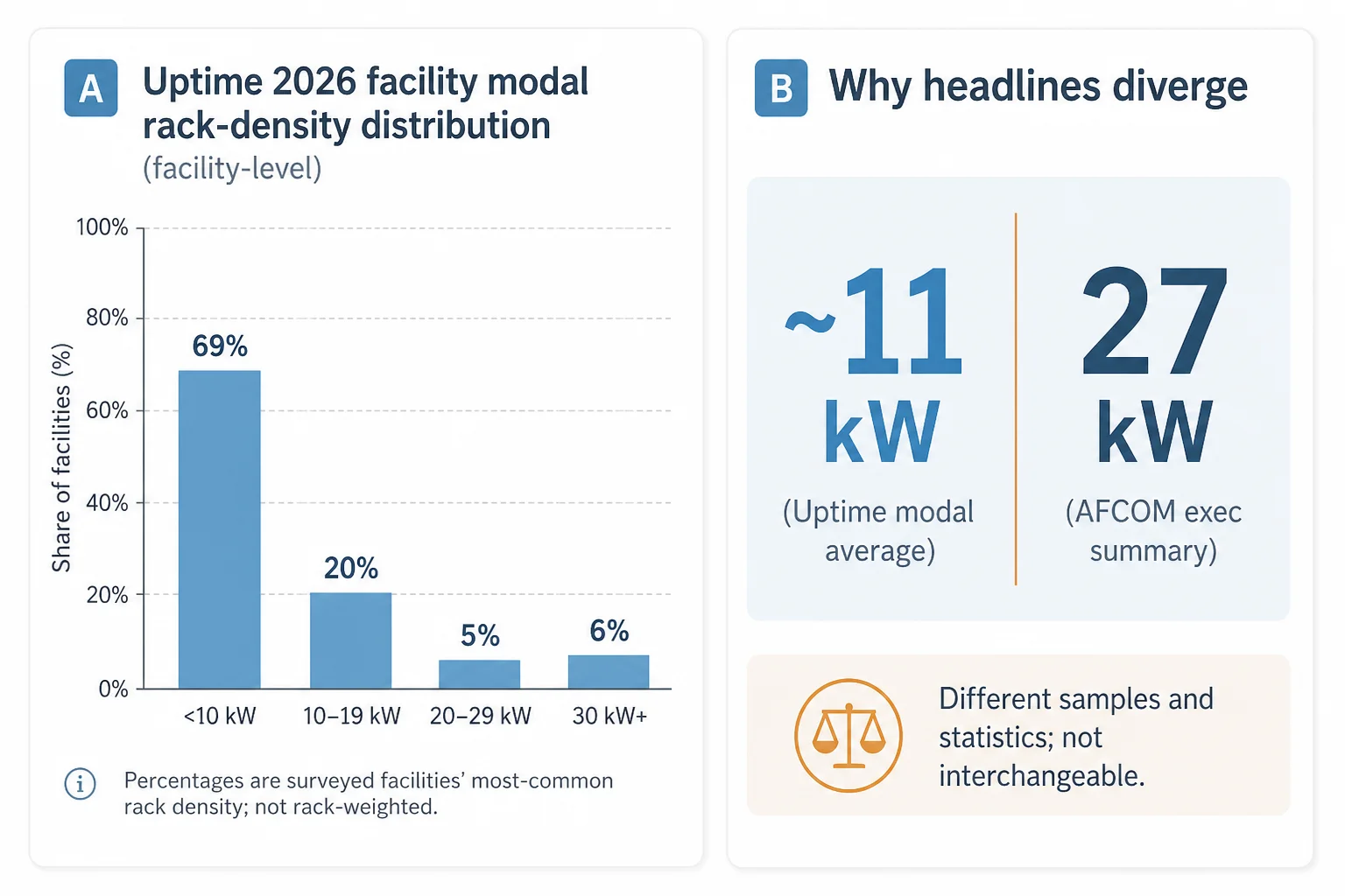
Some industry reporting measures something different again. A widely cited “16 kW in 2025 to 27 kW in 2026” figure traces to AFCOM’s 2026 State of the Data Center executive summary (compared with 7 kW in 2021), but the public executive summary does not disclose the weighting basis beyond “data center professionals”. The gap between AFCOM’s 27 kW and Uptime’s ~11 kW is too large to treat as interchangeable; it is better treated as a disputed measurement of different samples and statistical concepts, not a simple contradiction.
The reason this question stays live is legacy stock. In 2026, more than 27% of Uptime respondents said the data center in which they work is more than 15 years old, and Uptime states legacy facilities are not being retired at a pace matching new construction. Uptime’s 2025 survey produced a virtually identical figure (about 27.5% at 16 years or older). These are facility/respondent counts, not MW-weighted fleet age—but they explain why owners and operators keep facing the same decision: retrofit, rebuild, or re-scope the hall.
Uptime also reports, in an August 2026 capacity analysis, that 52% of surveyed facilities had built or upgraded dedicated high-density hall space in the preceding 12 months and 70% expected to do so in the next 12 months. The wording combines “built” and “upgraded”, so it does not provide a retrofit-versus-new-build ratio. There is also no credible public dataset that splits colocation capacity age by MW or provides a market-wide split of thermal retrofit versus rebuild.
Gate 1 — Structural capacity: slab-on-grade vs raised floor
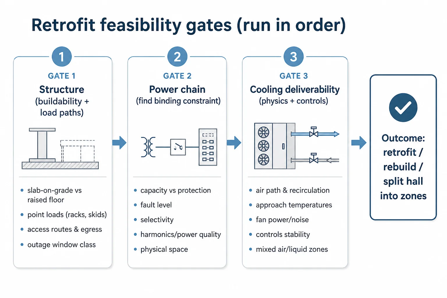
Structural capacity is often treated as a background discipline until a retrofit fails on it. For a density step-up, the structural question is not only “can the floor take more weight?” It is whether the hall can host the new load configuration (racks, containment changes, cable/busway changes, liquid distribution, and any new skids) without creating a remediation scope that is incompatible with outage windows and live operations.
Slab-on-grade halls
A slab-on-grade hall typically has more straightforward capacity for heavier point loads, but the retrofit still has structural gates: localised point-load checks where racks or skids concentrate mass; housekeeping-pad and plinth design; anchoring and vibration considerations; and the practical question of whether equipment can be brought in and positioned without compromising fire egress or live service routes. The remediation class tends to be local and buildable—if the slab and sub-base are adequate—but it still needs a documented load path and installation method.
Raised-floor halls
Raised-floor halls change the problem. The load is carried by pedestals, stringers, tiles, and the subfloor structure, and the failure modes are not subtle: local tile failure, pedestal buckling, or progressive issues once high loads are repeated across a row. Remediation can range from local reinforcement (stringers, load-spreading plates, pedestal upgrades) to partial reconfiguration of the underfloor plenum and services. That remediation has direct operational implications: access restrictions, contamination control, and sequencing around live cabling and airflow paths.
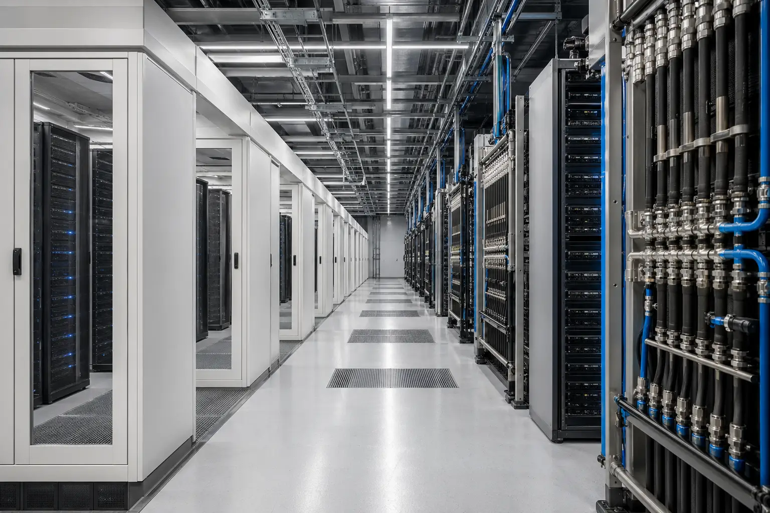
Liquid-cooled deployments add a specific retrofit reality: CDU skids should be treated as concentrated loads in the structural gate, not as “part of cooling” to be handled later. Even where the final rack arrangement is liquid-cooled, the hall still has air paths, return routes, and service corridors that must remain workable. A structural pass is therefore not only a calculation; it is a buildability decision that sets the project class.
Gate 2 — Power distribution sufficiency: find the binding constraint in the chain
After structure, the next gate is power distribution sufficiency. Retrofit failures usually come from treating “available power” as a single number. In practice, the constraint sits somewhere specific in the chain—and fixing one link can break another.
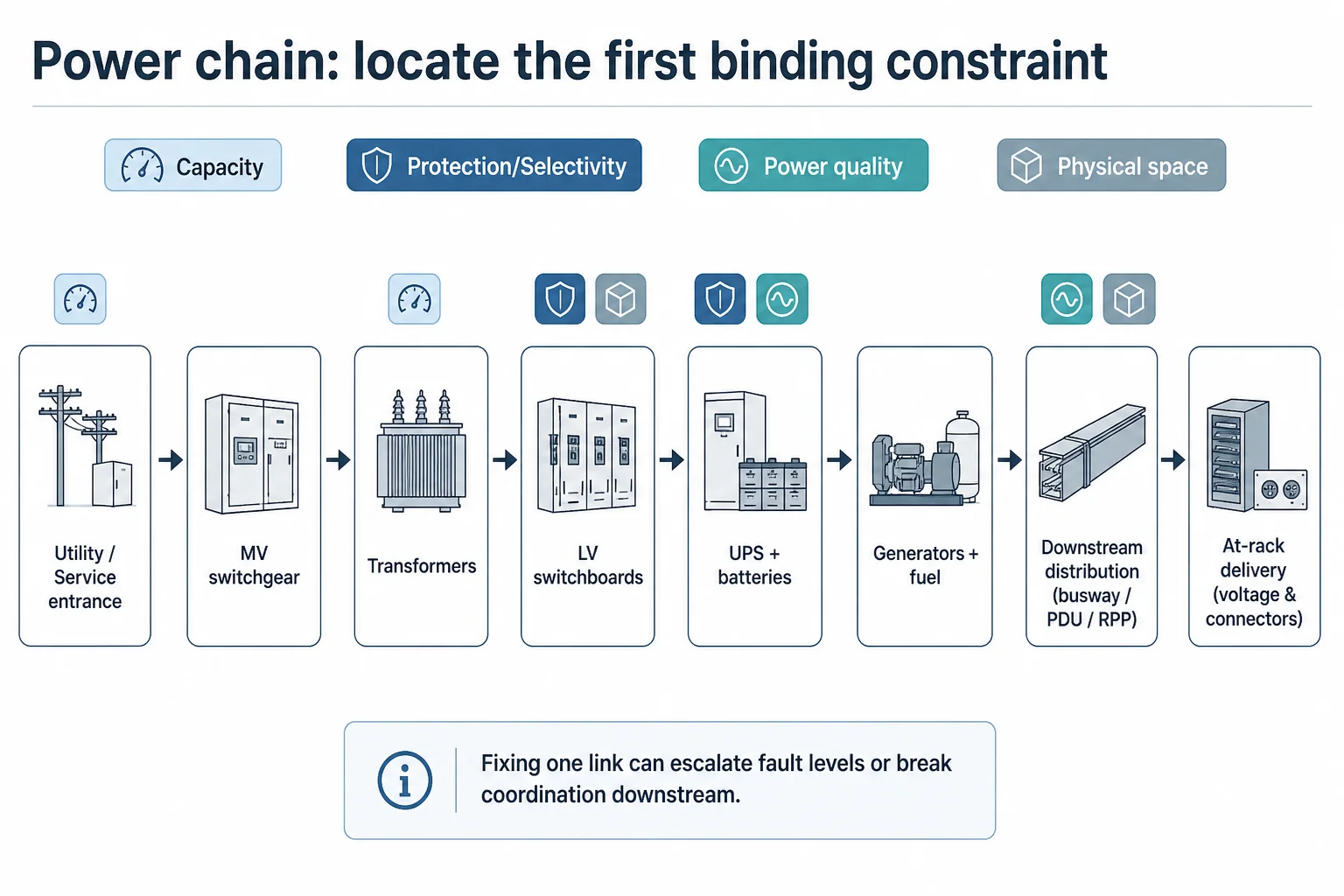
A practical way to run the assessment is to walk the chain from source to rack and ask, at each stage, whether the new load is blocked by capacity, by protection, by power quality, or by physical constraints. The chain typically includes: utility/service entrance or on-site generation; MV distribution and transformers; LV switchboards; UPS topology and battery runtime; standby generation and fuel logistics; downstream distribution (busway, PDU/RPP, whips); and at-rack delivery voltage and connector standards.
Common retrofit hard-stops in the power chain
- Switchboard and busway physical constraints: no spare ways, no space for extensions, or unsafe live-work requirements to modify.
- Fault level escalation: transformer upsizing or parallel feeds can push prospective fault currents beyond equipment ratings, forcing a wider replacement scope than expected.
- Protection coordination and selectivity: legacy breaker curves and new device characteristics can break discrimination, increasing the blast radius of faults.
- UPS and battery limits: higher density can shift the UPS from ‘resilience layer’ to ‘capacity limiter’, especially where runtime expectations are fixed.
- Power quality and harmonics: new PSU characteristics, variable-speed drives, and added conversion stages can trigger mitigation work that was not in the original scope.
- Voltage strategy mismatches: moving the at-rack delivery strategy (for example, away from 120/208 V toward higher-voltage distributions common in higher-density deployments) can cascade into PDUs, whips, monitoring, and safety procedures.
The goal is not to write a design in this gate. It is to locate the first binding constraint with enough confidence that the next engineering effort is spent on the right upgrade package—or on deciding that only part of the hall should be converted.
Gate 3 — Cooling capacity and topology: test deliverability, not nameplate
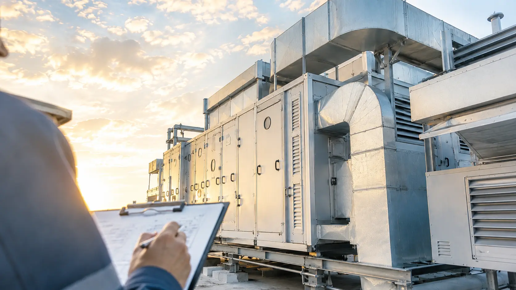
Cooling is where retrofit scopes often drift into “plant maths” and miss the real failure mode. The binding constraint is frequently deliverability: can the hall deliver the target inlet condition across the deployment zones without unacceptable fan power, hot-spot risk, noise, or operational fragility—and can the plant reject the heat at the required approach temperatures? Where the retrofit plan assumes warmer inlet targets for efficiency, the X-factor reliability metric is the tool for making the reliability cost of that setpoint change explicit.
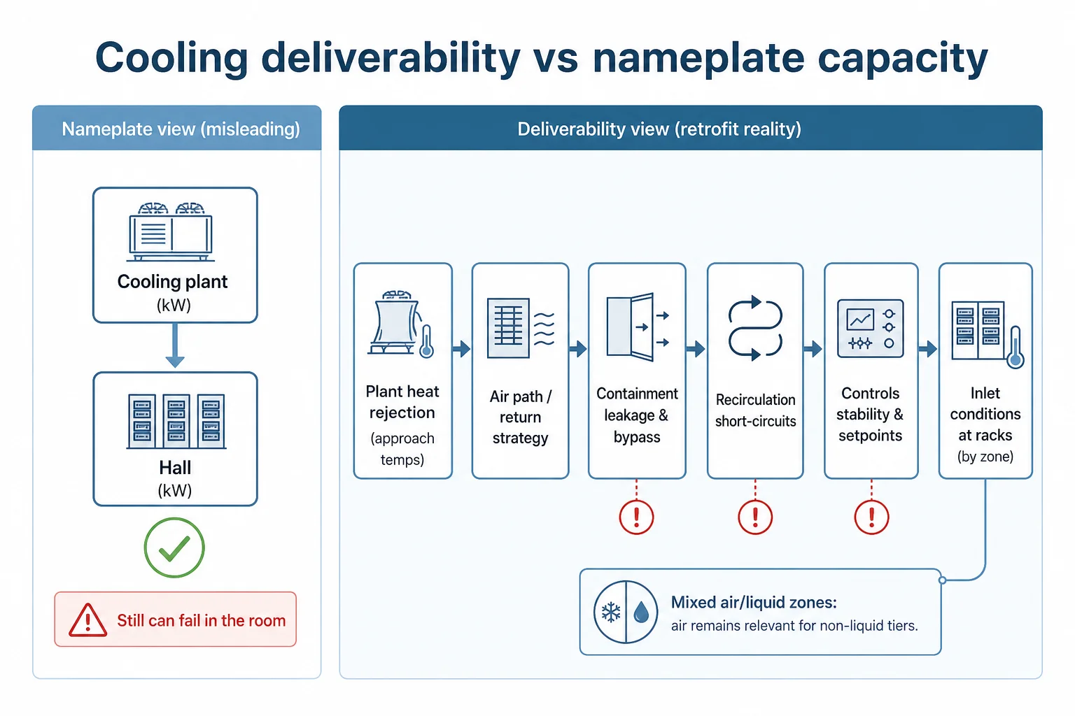
It is common to hear the claim that thermal capacity (rather than power or white space) is generally the binding constraint on colocation revenue. That market-level commercial claim is widely repeated but not well substantiated by suitable survey or market datasets. What is supportable is the narrower engineering phenomenon: airflow defects in a legacy hall can strand otherwise available cooling capacity, meaning the hall under-delivers even when nameplate capacity exists.
Measured field work by the US Department of Energy and Lawrence Berkeley National Laboratory has shown that bundled airflow corrections in an approximately 40-year-old facility can release stranded cooling capacity in a legacy hall. That evidence is bundled—those results are not attributable to containment alone—but it supports the engineering point that airflow and controls defects can be the limiter.
The AI conversion case: mixed air/liquid, not a single cutover
For AI conversion, current standards framing treats cooling as an integrated, mixed-architecture problem. The 2026 ASHRAE/NEMA/PNNL AI Data Center Energy Performance Framework discusses purpose-built AI facilities where densities routinely exceed roughly 50–120 kW/rack and positions liquid technology cooling systems, mixed air/liquid architectures, airflow management, and commissioning as one coupled design problem. It does not declare 30 kW or 40 kW as a universal physical air-cooling cutoff.
In heterogeneous facilities, mixed cooling is treated as an enduring feature: high-density GPU zones may use liquid while conventional x86, storage, networking, and lower-density tiers remain air cooled. In a retrofit, that matters because containment and airflow management may remain the right answer for the air-cooled tiers even if the marquee AI zone is liquid-cooled.
Where racks move to liquid cooling with CDUs, hot aisle containment is typically not the arrangement used for those liquid-cooled rows—but the hall does not become “air irrelevant”. The remaining air-cooled tiers still need a controlled supply/return path, and the hall’s remaining air path should be checked for recirculation risks created by the new physical arrangement, changed obstructions, and altered return-air behaviour. That recirculation check is a practical engineering step: it looks for new short-circuit paths and unintended mixing that can destabilise the air-cooled zones even when the liquid-cooled zone is performing.
Containment as a hall-level disposition (not a subsystem to ‘add’)
Retrofit guidance often treats containment as a single measure: “implement hot/cold aisle containment and seal gaps”. In operational halls, containment is better treated as a hall-level disposition. A hall may hold several containments, built at different times, with different leakage behaviours, different return paths, and different operational practices. The assessment therefore has two layers: whether the hall-level air path still makes sense, and whether conditions inside each containment are stable under the proposed load change.
The practical option set is broader than “keep or add”. It usually includes: reconfigure existing containment (geometry, doors, baffles, return path); introduce new containment in a specific zone; upgrade (reduce leakage, improve return control, improve controls sequencing); or replace entirely where the existing arrangement cannot be made stable or serviceable.
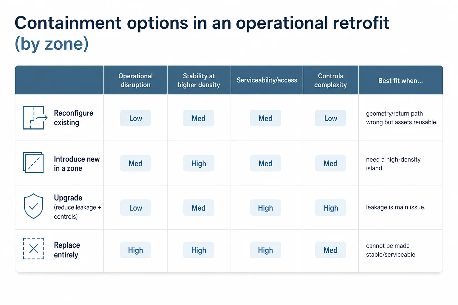
One paragraph on topology selection (bounded)
Topology choice (hot aisle vs cold aisle, return strategy, and how containment interacts with plant and controls) is a separate decision from “do we need containment work at all”. In retrofit, the key is to choose a topology that matches the hall’s air path, maintenance model, and failure tolerance, then verify it against the real obstructions and leakage paths that exist today.sive model.
One paragraph on verification (bounded)
Verification should be treated as a proof step before committing to rack moves. Typical verification methods include targeted measurement (temperature/pressure differentials, airflow where practical), controls trend analysis, and modelling where it is justified. CFD can be useful here, but it is one assessment method among several; the goal is to reduce uncertainty about hot-spot risk and recirculation under the proposed change, not to produce a visually impressive model.
The knock-on works: scopes that appear only once retrofit becomes real
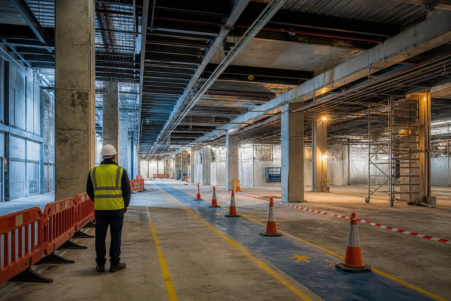
The most expensive surprises in retrofit are often not the headline upgrades. They are the knock-on works that appear when the retrofit is forced to be buildable in a live hall. If containment is reconfigured, if rack rows move, if liquid distribution is introduced, or if electrical distribution is reworked, other services can need recoordination or modification to stay compliant and maintainable.
- Lighting: changes to row geometry, containment roofs, or service corridors can require rework to maintain safe light levels and maintenance access.
- Fire detection and suppression: zoning, detector placement, and discharge strategy can be affected by new obstructions, altered air movement, or changed compartmentation assumptions.
- Monitoring and controls: additional sensors, new trend points, and sequencing changes are often required to make the new operating state observable and controllable.
- Physical access and serviceability: higher densities and tighter containment can make routine work harder; retrofit must preserve safe access routes and maintenance clearances.
- Water and environmental dependencies (where liquid is introduced): leak detection, drainage strategy, and maintenance isolation become part of the operational model.
Waste-heat capture and metering is increasingly a scope consideration even when it is not the main driver of the retrofit. The EU recast Energy Efficiency Directive, the European Commission’s data-center reporting and rating framework, and Dutch implementation under RVO are moving beyond pure reporting toward conditional waste-heat expectations—so retrofit scopes increasingly need a stated position on heat-capture boundaries and metering for credible net-zero data center claims, even if the decision is “not in this phase”.
Retrofit, rebuild, or split the hall: what cannot be decided without the specific facility
The decision at the end of a retrofit assessment is often one of three: retrofit the hall as planned, rebuild (or replace the hall’s core infrastructure), or split the hall into zones where only part is converted to the new load. Generic step lists cannot make that decision because the binding constraint is specific to the facility and because remediation cost is dominated by buildability, outages, and interfaces.
Typical outcomes from the constraint sequence
- Structural gate fails (especially on raised floors with heavy point loads): remediation may be programme-class and incompatible with live operations—often pushing toward rebuild or a smaller conversion zone.
- Power-chain gate fails late (fault levels, selectivity, physical switchboard constraints): the apparent ‘simple upgrade’ becomes a wider replacement scope; splitting the hall is often the risk-controlled option.
- Cooling deliverability fails despite nameplate: the fix may be airflow/controls corrections, containment rework, or a topology change; the right answer depends on whether the hall can be made stable and maintainable at the new density.
- Containment disposition is inconsistent across the hall: reconfiguration or replacement may be needed in only part of the space; treating containment as an assessed condition avoids over-scoping.
This is also where the only on-topic question that routinely appears in search behaviour becomes concrete: the downsides of retrofitting are not abstract. They are the cost of discovering a failed gate late, the operational risk of working inside a running hall, and the tendency for interface knock-ons (fire strategy, lighting, monitoring, access) to expand the scope beyond the original ‘upgrade’ narrative.
Retrofitting an operational hall under live constraints?
Azura supports owners and operators with constraint-led retrofit assessments: structural screens, power-chain feasibility, cooling deliverability checks, and buildable phasing aligned to outage windows.
Practical first moves for a live retrofit assessment
For an operational hall being tested against a new load, early effort should reduce uncertainty in the first gates before anyone commits to a detailed design package. In practice, that early gate work is often led within our data center consulting services that cover feasibility through technical due-diligence and MEP integration, so the eventual scope is evidence-led rather than assumption-led.
- Write the load change down as an engineering design basis: target rack classes by zone, growth path, uptime posture, and any known transient behaviour constraints.
- Run the structural screen first and explicitly separate slab-on-grade from raised-floor remediation options; treat CDU skids as concentrated loads in this screen.
- Map the power chain end-to-end and identify the first binding constraint (capacity, protection, power quality, or physical space) before designing ‘an upgrade’.
- Test cooling deliverability in the zones that will change first: measurement and trend review before modelling; use CFD only where it reduces a specific uncertainty.
- Inventory containment by zone (not as a single hall attribute): leakage condition, return path, serviceability, and how it interacts with controls sequencing.
- Create a knock-on register (fire, lighting, monitoring, access, water where relevant) and assign owners early so it does not appear as late scope creep.
Conclusie
A data center retrofit that works is not a collection of upgrades; it is a constraint-led decision about whether an operational hall can carry a changed load. The fastest way to avoid wasted design effort is to run the feasibility gates in order: structural capacity (with slab-on-grade and raised-floor treated differently), power distribution sufficiency (by locating the binding constraint in the chain), then cooling deliverability (tested as physics and controls, not nameplate).
Where AI conversion is the driver, mixed air/liquid architectures are now the normal framing rather than an all-or-nothing cutover. The practical end state is often not a single yes/no: it is retrofit, rebuild, or split the hall into zones with different density and cooling postures—chosen on documented gate outcomes rather than optimistic averages.
Make the retrofit decision on gate outcomes, not averages.
If a load change is driving an upgrade, Azura can help structure the feasibility gates and translate findings into outage-safe work packages and a defensible retrofit/rebuild/split recommendation.
Referenties
- Uptime Institute Global Data Center Survey 2026 — Uptime Institute (2026-01-01)
- Uptime Institute Global Data Center Survey 2025 — Uptime Institute (2025-01-01)
- State of the Data Center 2026 (Executive Summary) — AFCOM (2026-01-01)
- AI Data Center Energy Performance Framework — ASHRAE / NEMA / Pacific Northwest National Laboratory (2026-01-01)
- Best Practices Guide for Energy — Efficient Data Center Design (airflow management and stranded capacity concepts) — Lawrence Berkeley National Laboratory (2011-06-01)
- Directive (EU) 2023/1791 on energy efficiency (recast) — European Union (2023-09-20)
- European data center reporting: delegated act and supporting framework under the Energy Efficiency Directive — European Commission (2024-01-01)